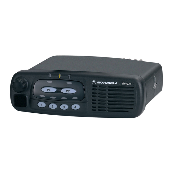
Motorola GM160 기본 서비스 매뉴얼 - 페이지 26
{카테고리_이름} Motorola GM160에 대한 기본 서비스 매뉴얼을 온라인으로 검색하거나 PDF를 다운로드하세요. Motorola GM160 46 페이지. Professional radio
Motorola GM160에 대해서도 마찬가지입니다: 서비스 정보 (34 페이지), 사용자 설명서 (44 페이지), 서비스 정보 (32 페이지), 서비스 정보 (32 페이지), 사용자 설명서 (44 페이지)

3-10
7.3
Radio Chassis and Transceiver Board
1.
Inspect the transceiver board chassis and if required reapply thermal grease to the heatsink
area on the chassis and heat dissipating devices. You may have to remove damaged thermal
pads from the chassis and devices prior to applying the grease.
2.
Insert the transceiver board at an angle (approximately 30°) into the chassis taking care to
slide the antenna connector and accessory connector into their cut-outs in the chassis.
3.
Lower the transceiver board onto the chassis and align the two locating holes in the board
with the locating pins in the chassis.
4.
Secure the cover to the chassis with the six screws previously removed.
5.
Torque the six screws to 1.9 NM (17 in lbs) using the T20 TORX™ driver. Begin with the two
screws located in the middle of the chassis followed by the four outer screws. Since the
screws usually take a set, torque the screws a second time (1.9 NM) in the same order.
6.
Refit the top cover over the assembled radio chassis. Press the cover down until it snaps into
place.
7.4
Control Head Fitting
1.
Align the "0" mark on the flex with the "0" mark on the chassis to the socket on the radio
assembly as shown in Figure 3-2.
2.
Check that the back housing o-ring seal is undamaged and fitted in the groove. Replace the
seal if it is damaged (refer to the exploded view diagrams and parts list).
3.
Fit the back housing to the control head. Ensure that the tags on the back housing align with
the snap catch grooves on the control head. Press the back housing into place until it snaps
into place.
4.
Check that the radio chassis o-ring seal is undamaged and fitted in the groove on the chassis
assembly. Replace the seal if it is damaged.
MAINTENANCE
