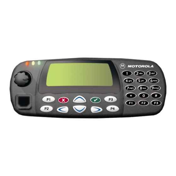
Motorola GM300 Series 기본 서비스 매뉴얼 - 페이지 36
{카테고리_이름} Motorola GM300 Series에 대한 기본 서비스 매뉴얼을 온라인으로 검색하거나 PDF를 다운로드하세요. Motorola GM300 Series 46 페이지. Professional radio

4-2
3.0
RF Test Mode
When the radio is operating in its normal environment, the radio's microcontroller controls the RF
channel selection, transmitter key-up, and receiver muting. However, when the unit is on the bench
for testing, alignment, or repair, it is removed from its normal environment and cannot receive
commands from its system. Therefore, the internal microcontroller does not key the transmitter or
unmute the receiver. This prevents the use of a normal tuning procedure. To solve this problem, a
special "test mode" is incorporated into the radio.
To enter test mode (display radios):
1.
Turn the radio on.
2.
Within ten seconds after the self test is complete, press button P2, five times in succession.
3.
After "CSQ CHXX SP25" appears in the display, the radio is on channel XX, carrier squelch
mode, 25 kHz channel spacing.
4.
Each additional press of P2 scrolls through to the next channel spacing and a corresponding
set of tones are sounded.
5.
Pressing P1 scrolls through and accesses test environments as shown in Table 4-2.
6.
Pressing P2 for three seconds switches the radio to the control head test mode. 'LCD Test'
appears on the display.
7.
Pressing P1 causes the radio to turn on all the dots of the first character. Another P1 press
turns on all the dots of the next character and so on until the last character.
8.
Pressing P1 at the end of the LCD test activates the 'Icon Test'. The next P1 press turns on
the first icon.
9.
Pressing P1 at the end of the Icon test activates the button test. Pressing any button (except
P1) or any keypad button during the LCD test or Icon test immediately activates this test.
10. Pressing P2 for 3 seconds in the control head test mode causes the radio to return to the RF
test mode.
To enter test mode (non display radios):
1.
Turn the radio on.
2.
Within ten seconds after the self test is complete, press button P2, five times in succession.
3.
All LEDs turn on for a short period to indicate the entry of the test mode.
4.
Each additional press of P2 scrolls through to the next channel spacing and a corresponding
set of tones are sounded.
5.
Pressing P1 scrolls through and accesses test environments as shown in Table 4-2.
6.
Pressing button 1 (up) or button 2 (down) scrolls through and accesses test channels as
shown in Table 4-4. The LEDs above the buttons 1 to 4 indicate the channel number in binary
form.
7.
Pressing P2 for three seconds activates the button test.
8.
Pressing P2 again for three seconds causes the radio to return to the RF test mode.
XX = channel number (01 - 14)
TRANSCEIVER PERFORMANCE TESTING
