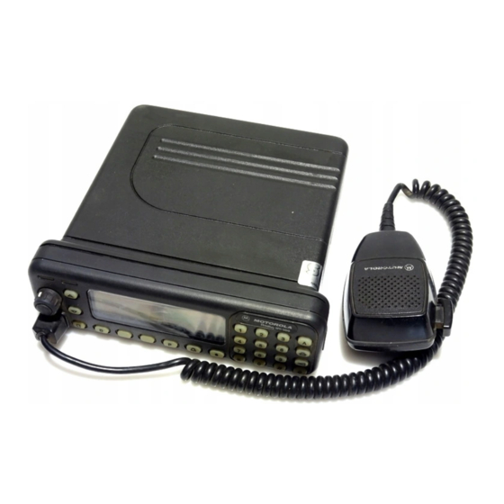
Motorola GM1200 Series 서비스 매뉴얼 - 페이지 19
{카테고리_이름} Motorola GM1200 Series에 대한 서비스 매뉴얼을 온라인으로 검색하거나 PDF를 다운로드하세요. Motorola GM1200 Series 28 페이지. Gm series professional radio
Motorola GM1200 Series에 대해서도 마찬가지입니다: 사용자 설명서 (19 페이지)

General Repair Procedures and Techniques
Chip Components
Use either the RLN4062 Hot-Air Repair Station or the Motorola 0180381B45 Repair Station for
chip component replacement. When using the 0180381B45 Repair Station, select the TJ-65 mini-
thermojet hand piece. On either unit, adjust the temperature control to 370 °C (700 °F), and
adjust the airflow to a minimum setting. Airflow can vary due to component density.
To remove a chip component:
1.
Use a hot-air hand piece and position the nozzle of the hand piece approximately 0.3 cm
(1/8") above the component to be removed.
2.
Begin applying the hot air. Once the solder reflows, remove the component using a pair
of tweezers.
3.
Using a solder wick and a soldering iron or a power desoldering station, remove the
excess solder from the pads.
To replace a chip component using a soldering iron:
1.
Select the appropriate micro-tipped soldering iron and apply fresh solder to one of the
solder pads.
2.
Using a pair of tweezers, position the new chip component in place while heating the
fresh solder.
3.
Once solder wicks onto the new component, remove the heat from the solder.
4.
Heat the remaining pad with the soldering iron and apply solder until it wicks to the
component. If necessary, touch up the first side. All solder joints should be smooth and
shiny.
To replace a chip component using hot air:
1.
Use the hot-air hand piece and reflow the solder on the solder pads to smooth it.
2.
Apply a drop of solder paste flux to each pad.
3.
Using a pair of tweezers, position the new component in place.
4.
Position the hot-air hand piece approximately 0.3 cm (1/8" ) above the component and
begin applying heat.
5.
Once the solder wicks to the component, remove the heat and inspect the repair. All
joints should be smooth and shiny.
2-3
