Motorola GM1280 서비스 정보 - 페이지 9
{카테고리_이름} Motorola GM1280에 대한 서비스 정보을 온라인으로 검색하거나 PDF를 다운로드하세요. Motorola GM1280 32 페이지. Gm series professional radio uhf (403-470mhz)
Motorola GM1280에 대해서도 마찬가지입니다: 서비스 정보 (34 페이지), 서비스 정보 (32 페이지)

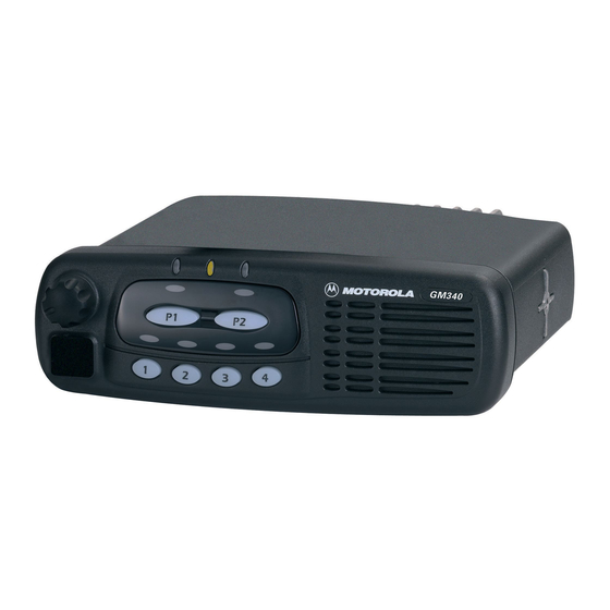
Controlhead Model for GM140, GM340 and GM640
An additional pair of analogue lines and A/D µP ports (PE 3 – 2) is available to support a keypad
microphone, connected to the microphone connector J0811. Any microphone key press is processed
the same way as a key press on the controlhead.
2.6
Status LED and Back Light Circuit
All indicator LED's (red, yellow, green) are driven by current sources. To change the LED status the
host radio sends a data message via SBEP bus to the controlhead µP . The controlhead µP
determines the LED status from the received message and switches the LED's on or off via port PB
7 – 0 and port PA4. The LED status is stored in the µP 's memory. The LED current is determined by
the resistor at the emitter of the respective current source transistor.
The back light for the keypad is controlled by the host radio the same way as the indicator LED's
using µP port PA 5. The µP can switch the back light on and off under software control. The keypad
back light current is drawn from the FLT A+ source and controlled by 2 current sources. The LED
current is determined by the resistor at the emitter of the respective current source transistor.
2.7
Microphone Connector Signals
Signals BUS+, PTT IRDEC, HOOK, MIC, HANDSET AUDIO, FLT A+, +5V and 2 A/D converter
inputs are available at the microphone connector J0811. Signal BUS+ (J0811-7) connects to the
SBEP bus for communication with the CPS or the Universal Tuner. Line MIC (J0811-5) feeds the
audio from the microphone to the radio's controller via connector J0801-4. Line HANDSET AUDIO
(J0811-8) feeds the receiver audio from the controller (J0801-6) to a connected handset. FLT A+,
which is at supply voltage level, and +5V are used to supply any connected accessory like a
microphone or a handset.
The 2 A/D converter inputs (J0811-9/10) are used for a microphone with keypad. A pressed key will
change the dc voltage on both lines. The voltages depend on which key is pressed. The µP
determines from the voltage on these lines which key is pressed and sends the information to the
host radio.
Line PTT IRDEC (J0811-6) is used to key up the radio's transmitter. While the PTT button on a
connected microphone is released, line PTT IRDEC is pulled to +5 volts level by R0843. Transistor
Q0843 is switched on and causes a low at µP port PA2. When the PTT button is pressed, signal PTT
IRDEC is pulled to ground level. This switches off Q0843 and the resulting high level at µP port PA2
informs the µP about the pressed PTT button. The µP will inform the host radio about any status
change on the PTT IRDEC line via SBEP bus.
When line PTT IRDEC is connected to FLT A+ level, transistor Q0821 is switched on through diode
VR0821 and thereby pulls the level on line ON OFF CONTROL to FLT A+ level. This switches on the
radio and puts the radio's µP in bootstrap mode. Bootstrap mode is used to load the firmware into
the radio's flash memory (See controller subsection for more details).
The HOOK input (J0811-3) is used to inform the µP when the microphone´s hang-up switch is
engaged. Dependent on the CPS programming the µP may take actions like turning the audio PA on
or off. While the hang up switch is open, line HOOK is pulled to +5 volts level by R0841. Transistor
Q0841 is switched on and causes a low at µP port PA1. When the HOOK switch is closed, signal
HOOK is pulled to ground level. This switches off R0841and the resulting high level at µP port PA1
informs the µP about the closed hang up switch. The µP will inform the host radio about any status
change on the HOOK line via SBEP bus.
2-3
