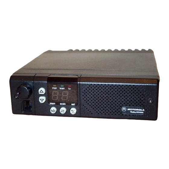
Motorola RADIUS GM300 서비스 매뉴얼 - 페이지 31
{카테고리_이름} Motorola RADIUS GM300에 대한 서비스 매뉴얼을 온라인으로 검색하거나 PDF를 다운로드하세요. Motorola RADIUS GM300 49 페이지. 16-channel, conventional fm radio
Motorola RADIUS GM300에 대해서도 마찬가지입니다: 서비스 매뉴얼 (28 페이지), 사용 설명서 (18 페이지), 사용 설명서 (19 페이지), 사용자 설명서 (37 페이지), 운영 지침 (2 페이지)

Theory of Operation
Logic Board
the logic board. Q277 conducts to supply TX 8.5V, and
Q278 saturates across the base-emitter of Q279, turning
it off.
Each VCO consists of a FET oscillator whose frequency
is determined by a parallel L-C network consisting of a
tunable coil and a network of varactors. As the steering
line varies over the range of 2V to 7.8V DC, the capaci-
tance of the varactors decreases as voltage is raised,
causing the oscillator frequency to increase. The trans-
mit VCO has an additional varactor, CR208, which is
very lightly coupled to the tank circuit, which provides
frequency modulation of the VCO from the audio sig-
nal applied at J6-10 and adjusted by VCO MOD adjust
pot R302.
Each VCO has an AGC rectiÞer circuit (CR206 or
CR214) which varies the DC gate bias on the VCO FET
as a function of the RF output level at the VCOÕs drain.
This helps maintain a more constant VCO output level,
and prevents RF voltages from increasing to levels
which might cause rectiÞcation by the varactors.
Transistors Q204, Q205 are receive buffer ampliÞers.
These raise the RF output of the VCO to the level
required as injection for the Þrst mixer, typically
between +5 and +13 dBm depending on the frequency
band, as detailed in sections 1.1 and 1.2. The RF at
Q205Õs base is sampled and fed back to the synthesizer
via buffer Q107, allowing the synthesizer to ÒknowÓ if
the VCO is operating at the correct frequency.
Similarly, transistors Q207, Q208 are transmit buffer
ampliÞers. These raise the RF output of the VCO to the
level required by the RF power ampliÞer, typically +13
to +14.5 dBm, as measured at J5, which is a 50 ohm
port. The VCO frequency is sampled at Q208Õs base
and fed back to the synthesizer via buffer Q107.
Logic Board
There are two versions of logic boards used in GM300
series mobile radios, ÒmaskedÓ and Òexpanded.Ó The
expanded logic board has a shielded compartment
which encloses the microcomputer, custom gate array,
and external memory ICÕs, and has a four-layer printed
circuit board layout. The masked logic board uses a
two- layer circuit board without the shielded compart-
ment, with all software functions contained in a single
masked microcomputer IC. In general, the masked
logic board is used in 2 and 8 channel models with
basic signaling capabilities, while the expanded logic
board is found in 16 channel models having more elab-
orate signaling systems or requiring programmable
accessory connector I/OÕs.
The logic board circuitry consists of Þve major sections:
¥ DC distribution and regulation
¥ Microcomputer and logic
2-6
¥ Receiver audio circuitry
¥ Transmitter audio circuitry
¥ Transmitter power control circuitry
DC Distribution and Regulation
All operating voltage for the radio is supplied from the
RF power ampliÞerÕs battery input connector J2. This
voltage is protected from reverse polarity or excessive
positive transients by CR2270, CR2370, CR2470,
CR2570, CR2670 or CR2770 (depending on power
ampliÞer kit), which acts as a power diode for reverse
polarity protection, as well as a power transient sup-
pressor due to its reverse avalanche characteristics. The
supply voltage is routed to the logic board via J7-5
(UNSW B+).
Whenever UNSW B+ is supplied, a continuous source
of 5V DC is applied to pin 2 of the microcomputer from
the RAM 5V supply (VR402, CR403, R410 and C408).
This maintains the radioÕs scan list, current operating
mode, etc., when the radio is turned off. Due to the
storage of C408, this information can be maintained for
up to several hours even if the battery supply voltage
is interrupted.
When ignition control is not used, UNSW B+ via fuse
F801 becomes B+ which is routed through the on-off
switch to become SW B+. When ignition control is
used, fuse F801 is removed, and the vehicleÕs ignition-
switched voltage is supplied to J3-10 which is the B+
that is routed through the on-off switch to become SW
B+. Thus, with ignition control, ignition-controlled
voltage must be present at J3-10 for the radio to oper-
ate.
In 2-layer masked logic boards, when the radio is
turned on, SW B+ turns on Q404 via R414, which then
turns on Q403 via R412. When Q403 is on, UNSW B+ is
applied to to the supply pins of opamps U401 and
U451 (energizing the 9.6 volt regulator and transmitter
power control circuits). The low saturation voltage of
Q403 keeps the supply voltage of the transmitter
power control circuit essentially equal to the UNSW B+
voltage present in the RF Power AmpliÞer. This is
important for accurate power control operation. SW B+
is also routed to 5 volt regulator U402 (powering the
microcomputer and logic circuitry) and to J3-13, the
SW A+ sense pin on the accessory connector. The cur-
rent drawn through the on-off switch is relatively low,
less than 400 mA, and the majority is that required by
the 5V regulator. All high current stages, such as the RF
and audio power ampliÞers, operate from UNSW B+
and are controlled by low currents.
In 4-layer expanded logic boards, power distribution is
similar except that Q403 also switches the supply volt-
age to the 5 volt regulator IC U402. The higher current
drain from the 5V regulator due to the expanded logic
circuitry does not need to ßow through the radioÕs on-
68 No.
Name of Manual
March, 1997
