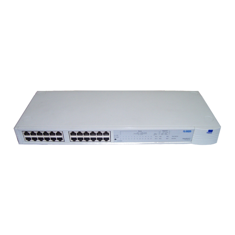
3Com SuperStack II 사용자 설명서 - 페이지 2
{카테고리_이름} 3Com SuperStack II에 대한 사용자 설명서을 온라인으로 검색하거나 PDF를 다운로드하세요. 3Com SuperStack II 4 페이지. Switch matrix module
3Com SuperStack II에 대해서도 마찬가지입니다: 사용자 설명서 (9 페이지), 사용자 설명서 (2 페이지), 보충 자료 (1 페이지), 중요 정보 (2 페이지), 사용자 설명서 (6 페이지)

Handling the Module
The module can be easily damaged by electrostatic discharge.
To prevent damage, please observe the following:
Do not remove the module from its packaging until you are
ready to install it into a switch.
Do not touch any of the pins, connections or components
on the module.
Handle the module only by its edges and front panel.
Always wear an anti-static wristband connected to a
suitable earth point.
Always store or transport modules in appropriate
anti-static packaging.
Fitting the Module
To install the module into the switch:
1 Ensure that the switch is disconnected from the mains power
supply and you are wearing an anti-static wristband
connected to a suitable earth point.
2 Using a small cross-bladed screwdriver, remove the blanking
plate from the rear of the switch. Do not remove any other
screws from the rear of the switch.
3 Keep the blanking plate and screws in a safe place. If you
remove the module at any time, you must replace the blank-
ing plate to prevent dust and debris entering the switch and
to aid the circulation of cooling air.
4 Hold the module so that the text on the front panel is oriented
correctly, and position the PCB onto the guide rails inside the
switch. Push the module fully into the switch, ensuring the
connectors are fully engaged. Tighten the two captive thumb-
screws securing the module.
Figure 1 Inserting the module into the switch
Connecting Cables and Powering Up
Each port supports half duplex and full duplex operation:
In half duplex mode, the fiber optic segment cannot
exceed 450m (1476ft) in length.
In full duplex mode, the fiber optic segments cannot
exceed 2km (6562ft) in length.
Use 62.5/125 micron 100BASE-FX fiber optic cable with SC
connectors.
Connect the module:
1 Remove the protective plastic covers from the fiber
connections on the module.
2 Ensure that the switch is powered up.
3 Plug the SC connector on the fiber cable into the fiber socket
on the module.
4 Connect the other end of the fiber optic segment to an appro-
priate 100Mbps device.
5 Check LEDs to ensure correct operation.
