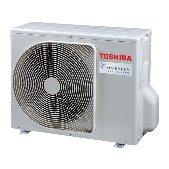
Toshiba 13343 설치 매뉴얼 - 페이지 11
{카테고리_이름} Toshiba 13343에 대한 설치 매뉴얼을 온라인으로 검색하거나 PDF를 다운로드하세요. Toshiba 13343 18 페이지.

Outdoor Unit
6
Refrigerant piping
CAUTION
Install in rooms that are 5 m
a leak of refrigerant gas occurs inside the
room, an oxygen defi ciency may occur.
Detaching the Valve cover
Remove the 5 screws.
• Pull the valve cover in the direction of the arrow, and remove it.
Refrigerant Piping Connection
Flaring
1. Cut the pipe with a pipe cutter.
90°
2. Remove the burr inside of the pipe.
When removing the burr, be careful so that chips do not fall into the pipe.
3. Remove the fl are nuts attached to the outdoor/indoor unit, then insert them
into each of the pipes.
4. Flare the pipes.
See the following table for the projection margin (A) and fl aring size (B)
A
Die
Pipe
Pipe
A
Rigid
Imperial
Outside
(clutch
Thickness
diameter
type)
nut type)
R32 tool
R32 tool
mm
mm
mm
6.35
0.8
0 to 0.5
9.52
0.8
0 to 0.5
12.7
0.8
0 to 0.5
CAUTION
• Do not scratch the inner surface of the
fl ared part when removing burrs.
• Flare processing under the condition of
scratches on the inner surface of fl are
processing part will cause refrigerant gas
leak.
or larger. If
3
Valve cover
Obliquity
Roughness
Warp
B
B
Flare Nut
Width
(wing
across
Tighten torque
fl at
mm
mm
mm
N•m
1.5 to
14 to
9.1
17
2.0
18
1.5 to
33 to
13.2
22
2.0
42
2.0 to
50 to
16.6
26
2.5
62
Pipe connection
1. Make wire and pipe connections for each indoor unit separately.
2. Align the centres of the connecting pipes and tighten the fl are nut as much
as possible with your fi ngers, then tighten the nut using a torque wrench.
Be sure to tighten the nut at the specifi ed torque value.
• If you use one outdoor unit for several indoor units of a different class,
connect the largest one fi rst A, then connect the rest in the order B to C.
• Do not remove the fl are nuts for any ports you are not going to use for
connection.
• Do not leave the fl are nut unattached for a long period of time.
• Use a different-diameter joint if the diameters of the connection port and
connection piping are different.
• Mount the different-diameter joint on the connection port of the outdoor
unit.
CAUTION
• KEEP IMPORTANT 6 POINTS FOR
PIPING WORK.
(1) Take away dust and moisture (inside
of the connecting pipes).
(2) Tighten the connections (between
pipes and unit).
(3) Evacuate the air in the connecting
pipes using a VACUUM PUMP.
(4) Check gas leak (connected points).
(5) Be sure to fully open the packed
valves before operation.
(6) Reusable mechanical connectors
and fl ared joints are not allowed
indoors. When mechanical
connectors are reused indoors,
sealing parts shall be renewed.
When fl ared joints are reused
indoors, the fl are part shall be
refabricated.
Air Purge
From the sake of environmental protection, use a vacuum pump to extract the
air during installation.
* Prepare a 4 mm hexagon wrench.
kgf•m
1. Connect a charge hose.
1.4 to
• Make sure that the Handle Hi of the gauge manifold valve is closed fully.
1.8
• Connect the port of the gauge manifold valve and the service port
3.3 to
(Valve core (Setting Pin)) using the charge hose.
4.2
NOTE
5.0 to
If a control valve or charge valve is attached to the charge hose, leak
6.2
of R32 refrigerant can be avoided.
2. Open the Handle Low of the gauge manifold valve fully, then operate the
vacuum pump.
• Loosen the fl are nut of the at the gas end a little to make sure that air is
taken in, then tighten the nut.
• If you fi nd air is not taken in, make sure that the charge hose is
connected to the port(s) securely.
• Perform extraction for about 15 or more minutes and make sure that the
compound pressure gauge reading is –101 kPa (–76 cmHg).
• If the compound pressure gauge reading is not –101 kPa (–76 cmHg),
there is a possibility air is being taken in from the port(s).
• Make sure that the charge hose is connected to the port(s) securely.
10
Installation Manual
EN
FR
DE
IT
ES
PT
GR
PL
CZ
