ABB ACS250 사용자 설명서 - 페이지 2
{카테고리_이름} ABB ACS250에 대한 사용자 설명서을 온라인으로 검색하거나 PDF를 다운로드하세요. ABB ACS250 2 페이지. Relay output option card

EXPLANATION
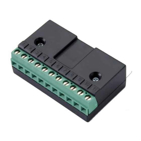
The Relay Output Module can be used in applications where the
analog/digital output from the drive is converted to a relay output.
Typical applications are where two relay outputs are required. The
functions of the relays are programmable in the drive and can be
any of the following:
o
Drive enabled
o
Drive healthy
o
Drive at set speed
o
Drive at zero speed
o
Drive at max speed
o
Motor in overload
OPTION CONTROL TERMINALS
1
2
3
4
* Analog inputs should be connected to terminals 6 & 7.
Note :
The second relay output contacts are available on terminals 8 and 9.
This relay utilises the drive's analog/digital output for operation -
therefore the analog output is not available when this module is
fitted.
NOTES
5
6
7
8
9 10 11
SPECIFICATIONS
Max Relay switching voltage:
Max Relay switching current:
Max input voltage :
Environmental :
Conformity :
OPERATION
Programming the first relay output
Since the first relay output (fitted within the ACS250/ACS255 (115V-
480V Variant) is programmed using parameter 1401 in the drive,
two completely independent relay outputs are available. The
following options are supported for relay 1 :
1401
0 : Drive enabled
1 : Drive healthy
2 : Motor at target speed
3 : Drive tripped
4 : Motor speed >= limit
5 : Motor current >= limit
6 : Motor speed < limit
7 : Motor current < limit
Programming the second relay output
The second relay output is controlled using parameter
1501. This can be set to any of the choices 0-7 as described below:
0 : Drive enabled
1 : Drive healthy
2 : Motor at target speed
3 : Drive tripped
4 : Motor speed >= limit
5 : Motor current >= limit
6 : Motor speed < limit
7 : Motor current < limit
Note : Parameters 1401,1501, and 3200 are located in the Long
parameter group, group navigation is detailed in the drive manual.
82-2ROUT-ABB_V2
COMMUNICATION INTERFACE
ACS250/ACS255 RJ45 Port Connections
Relay 1 output function select (RO1)
Defines the function of the user relay 1,
when the operating conditions are met.
Disabled : Contacts open
Enabled : Contacts closed
Options 4 to 7: the Relay output is
enabled using the level set in
parameter 3200
1501
Relay 2 output function select (RO2)
Defines the function of the user relay 2,
when the operating conditions are met.
Disabled : Contacts open
Enabled : Contacts closed
Options 4 to 7 : the Digital output is
enabled using the level set in
Parameter 3200.
250V AC / 220V DC
1A
+/- 50V DC
-10ºC ... +50ºC
IP00, UL94V-0
