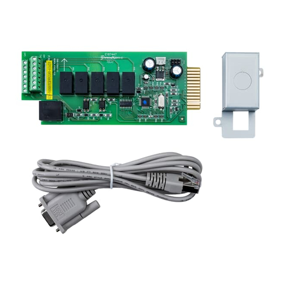
ABB AS400 사용자 설명서 - 페이지 5
{카테고리_이름} ABB AS400에 대한 사용자 설명서을 온라인으로 검색하거나 PDF를 다운로드하세요. ABB AS400 14 페이지. Relay card

1.3.1
Interface (14 pin Dry Contact Connector and RJ45)
The dry contact connector is organized according to the following table:
Segment
PIN Number
Segment 1
Pin 9 and Pin 2
Segment 2
Pin 10 and Pin 3
Segment 3
Pin 11 and Pin 4
Segment 4
Pin 12 and Pin 5
Segment 5
Pin 13 and Pin 6
Segment 6
Pin 8 and Pin 1
Segment 7
Pin 14 and Pin 1
Segment 8
Pin 7 and Pin 1
RS232 (RJ45 cable to DB9F)
TXD2
RJ45, Pin 3
RXD2
RJ45, Pin 6
GND
RJ45, Pin 4
Notes:
1
When closing the contact USER SW2, the AS400 Relay Card will send a command to the UPS to turn it on.
2
When closing the contact USER SW3, the AS400 Relay Card will send a command to the UPS to turn it off.
3
Do not close the contacts USER SW2 and SW3 at the same time.
4
Segment 7 (pin 14 and pin 1 / USER SW2) is fixed to "UPS On" function.
5
Segment 8 (pin 7 and pin 1 / USE SW3) is fixed to "UPS Off" function. (Refer to Section 1.3.3.1)
Specification/Function
240 Vac/1A(Max) or 30 Vdc/1A(Max)
240 Vac/1A(Max) or 30 Vdc/1A(Max)
240 Vac/1A(Max) or 30 Vdc/1A(Max)
240 Vac/1A(Max) or 30 Vdc/1A(Max)
240 Vac/1A(Max) or 30 Vdc/1A(Max)
NA
NA
NA
12Vdc 3mA (Max)
12Vdc 5mA (Max)
GND
Table 1: Dry Contact Pin Assignment
Figure 3: Segment illustration
4NWP100446R0001_OPM_ABB_AS400RelayCardPowerValue_EN140226
Modifications reserved
Remark
Output signal , NO or NC
Output signal , NO or NC
Output signal , NO or NC
Output signal , NO or NC
Output signal , NO or NC
Input signal (The external contact must be
closed between pin 8 and pin 1)
Input signal (The external contact must be
closed between pin 14 and pin 1)
Input signal (The external contact must be
closed between pin 7 and pin 1)
Power system GND
Page 6/15 ABB
