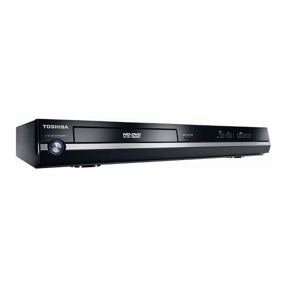
Toshiba HD-E1KE 서비스 매뉴얼 - 페이지 4
{카테고리_이름} Toshiba HD-E1KE에 대한 서비스 매뉴얼을 온라인으로 검색하거나 PDF를 다운로드하세요. Toshiba HD-E1KE 32 페이지. Toshiba hd-e1ke hd dvd player service manual

Touch current check
(After completing the work, measure touch current to prevent an electric shock.)
・Plug the AC cord directly into the AC outlet. Do not use an isolation transformer for this check..
・Connect a measuring network for touch currents between each exposed metallic part on the set and a good earth
ground such as a water pipe, as shown in Figure D.1
・The potential at any point(TOUCH CURRENT) expressed as voltage U
The part or contact of a TERMINAL is not HAZARDOUS LIVE if:
a) the open-circuit voltage does not exceed 35 V (peak) a.c or 60 V d.c.,
or,if a)is not met,
b) the measurement of the TOUCH-CURRENT shall be carried out in accordance with IEC 60990, with the measuring network
described in annex D of this standard.
The TOUCH CURRENT expressed as voltages U
- for a.c.:U
= 35 V(peak)and U
1
- for d.c.:U
= 1,0 V,
1
NOTE 5 -The limit values of U
mA 2,0mA d.c.
The limit value U
= 35 V (peak) for a.c. corresponds to the value 70mA (peak) a.c. for frequencies greater than 100 kHz.
1
Test TERMINALS
Resistance values in ohms(Ω)
V: Voltmeter or oscilloscope
(r.m.s or peak reading)
NOTE-Appropriate measures should be taken to obtain the correct value in case of non-sinusoidal waveforms.
The measuring instrument is calibrated by comparing the frequency factor of U
IEC 60990 at various frequencies. A calibration curve is constructed showing the deviation of U
curve as a function of frequency.
TOUCH CURRENT=U
=0.35 V (perk);
2
=0.35 V (peak) for a.c. and U
2
Measuring network for TOUCH CURRENTS
Rs=
A
1 500Ω
B
Input resistance: ≧1 MΩ
Input capacitance: ≦ 200 pF
Frequency range: 15 Hz to 1 MHz and d.c. respectively
/500(peak value)
2
and U
, does not exceed the following values:
1
2
=1.0 V for d.c. correspond, to the values 0,7mA (peak) a.c. and 2,0
1
Annex D
(normative)
Cs=
0.22uF
10kΩ
R
b
=
500Ω
U
1
Fig.D.1
and U
does not exceed the following value:
1
2
(V)
U
V
0.022uF
2
IEC 802/96
with the solid line in figure F.2 of
2
2
from the ideal
