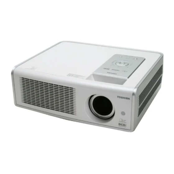
Toshiba TDP-MT700 서비스 매뉴얼 - 페이지 9
{카테고리_이름} Toshiba TDP-MT700에 대한 서비스 매뉴얼을 온라인으로 검색하거나 PDF를 다운로드하세요. Toshiba TDP-MT700 49 페이지. Home theater projector
Toshiba TDP-MT700에 대해서도 마찬가지입니다: 소유자 매뉴얼 (34 페이지), 소유자 매뉴얼 (36 페이지)

MT700 Service Manual
4. Circuit Operation
4.1. System Block Diagram
MT700 consist of the connector, main, chip board. The connector board provides the input
terminal and RS-232 for service ,video input(Composite, S-video, YcbCr) and graph
input(RGB BNC , Y Pb Pr). The main board provides the A/D converter for the graph input
(HDMI, RGB BNC, YPbPr) and decoder function for the video input. That supports also the
scaler and color process function. For the interlace video, the board supports the de-
interlace function. Besides, the boards provide the color wheel driver ,the lamp enable
functions and DMD chip control function.
This video projector can accept the following six kinds of input sources:
(1) HDMI
(2) RGBHV
(3) Component 1
(4) Component 2
(5) S-Video
(6) Composite
As shown in the system block diagram, there are seven boards in the system. They are:
(1) Main Board
(2) DMD Chip Board
(3) Thermal Sensor Board
(4) Color Wheel Sensor Board
(5) Keypad Board
(6) Ballast
(7) Power board
(8) IR board
In the main board circuits, it contains AD converter (AD9883), HDMI receiver (SII9993),
Video decoder (SAA7118), de-interlace processor (FLI2310), Scalar (OPLUS RM-103) and
CPU (RDC2021).
8
