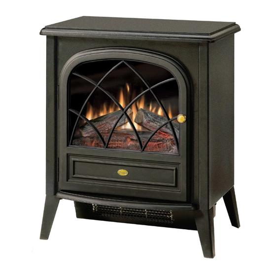
Dimplex ELECTRALOG CS4416 서비스 매뉴얼 - 페이지 7
{카테고리_이름} Dimplex ELECTRALOG CS4416에 대한 서비스 매뉴얼을 온라인으로 검색하거나 PDF를 다운로드하세요. Dimplex ELECTRALOG CS4416 13 페이지. Compact stove
Dimplex ELECTRALOG CS4416에 대해서도 마찬가지입니다: 소유자 매뉴얼 (14 페이지), 서비스 매뉴얼 (13 페이지), 서비스 매뉴얼 (11 페이지)

2. Remove the 11 Philips screws that attach the top panel
to the stove as shown in Figure 4. There are: four (4)
screws along each side; and three (3) screws at the front,
accessible behind the door.
3. Remove top panel.
4. Locate switch to be replaced and disconnect the wiring
clips, noting their original locations.
3 Position Switch
The 3 Position Switch is located in the far upper left corner
at the back of the stove (Figure 5). The Switch has three (3)
wire clips to remove.
Heater ON/OFF Switch
The Heater ON/OFF Switch is located in the far upper left
corner at the back of the stove, under the 3 Position Switch
Figure 5
Retainer Clip
3 Position
Switch
Heater
ON/OFF
Switch
(Figure 5). The Switch has two (2) wire clips to remove.
5. Depress the two (2) retainer clips on the switch to be
replaced (one (1) per side) and push the switch out from
the back panel of the stove.
6. Properly orient replacement switch and push into back
panel until retainer clips snap into place.
7. Reconnect switch with wire clips removed in step 4.
8. Reattach top panel to stove using screws removed in
step 2.
Flicker Motor/Flicker Rod Replacement
If the stove was operating prior to servicing allow at least
10 minutes for light bulbs and heating element to cool off to
avoid accidental burning of skin.
Disconnect power before attempting any maintenance or
cleaning to reduce the risk of electric shock or damage to
persons.
Replacement Procedure:
Wire Clips
Thermostat
Thermostat
Knob
1. Open stove door.
2. Remove the 11 Philips screws that attach the top panel to
the stove as shown in Figure 4 (page 6). There are: four
(4) screws along each side; and three (3) screws at the
front, accessible behind the door.
3. Remove top panel.
4. Slide partially reflective glass up from within the stove to
remove.
Figure 6
Partially
Reflective
Glass
Log Set Screws (2)
5. Remove the log set by removing the two (2) inside Philips
screws as shown in Figure 6.
6. Pull Flicker Rod as far right (towards Flicker Motor) as
possible and remove by cautiously bending the rod just
enough for it to clear the mounting bracket on the left.
7. Close the stove door and turn the stove onto its back.
Figure 7
7
Top Panel
Flicker Rod
Screws to remove
Flicker
Motor
