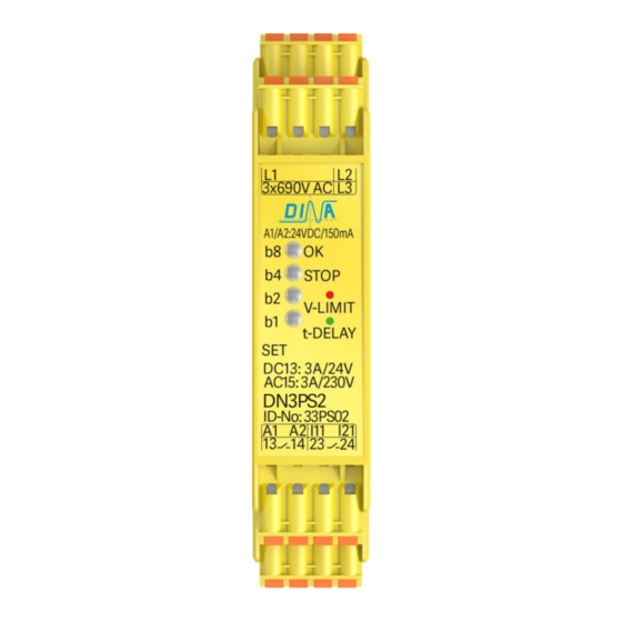
DINA DN3PS2 원본 사용 설명서 - 페이지 8
{카테고리_이름} DINA DN3PS2에 대한 원본 사용 설명서을 온라인으로 검색하거나 PDF를 다운로드하세요. DINA DN3PS2 16 페이지. Standstill monitoring for one and three phases motors without sensor system
DINA DN3PS2에 대해서도 마찬가지입니다: 원본 사용 설명서 (12 페이지)

DN3PS2
Anzeige
Anzeige
• Nach Anlegen der Betriebsspannung an die Klemmen
A1 und A2 erfolgt zunächst ein Eigentest.
• Während dessen bleiben die Ausgangskontakte in
Ruhestellung und die LED OK leuchtet rot (2a).
• Das Gerät ist betriebsbereit nach fehlerfreiem Test,
sichtbar durch die grün leuchtende LED OK (2b).
b8
b4
b2
b1
Gerätetest
Anzeige
Unit Test
Überwachte Funktion
• Die Stillstandserkennung erfolgt durch die
Auswertung der induzierten Spannung (EMK) bei
auslaufendem Motor.
• Die Ausgangskontakte öffnen unverzögert, wenn die
EMK-Spannung die am Gerät eingestellte Spannung
überschreitet. Die LED STOP erlischt (2c).
• Bei Unterschreitung der eingestellten Spannung
läuft der einstellbaren Einschaltverzögerung.
Die LED STOP blinkt grün (2d).
• Am Ende der Verzögerungszeit schließen die
Ausgangskontakte.
Die LED STOP leuchtet grün (2b).
• Mechanische Blockade des Motors ist nicht
überwacht.
I11 I21
Funktionsart
0V 0V
FA1
24V 0V
Nicht erlaubt
0V 24V
Nicht erlaubt
24V 24V
FA2
DN3PS2
OK
b8
OK
Stop
Stop
b4
P1
b2
P1
P2
P2
b1
2A
2B
Stillstand
Standstil
Tabelle 1
Funktion
geschlossen nur im Stillstand
geschlossen auch in Bewegung
Stand: 18.04.2018
Display
• After the connection of the power supply to the termi-
nals A1 and A2 an internal test is started.
• During this test the output contacts are open and the
LED OK is illuminated red (2a).
• The unit is ready after a faultless test displayed via the
green illuminated LED OK (2b).
b8
OK
b8
Stop
b4
b4
b2
P1
b2
b1
P2
b1
2C
2D
Bewegung
Auslauf
Movement
Run-out
Monitored function
• The detection of standstill happens via the measuring
of the electromotive force (EMF) after the running-out
of the drive.
• The output contacts open immediately if the EMF
value at the unit is higher than the adjustable voltage
value. The LED STOP is not illuminated (2c).
• With the undercut of the adjusted voltage the process
of the switch on time delay starts.
LED STOP is flashing green (2d).
• At the end of the adjustable time delay the output
contacts close (NO contacts).
The LED STOP is illuminated green (2b).
• A mechanical blockade of the drive is not
monitored.
Function mode
FM1
Not allowed
Not allowed
FM2
Seite 8 von 16
Date: 2018-04-18
OK
Stop
P1
P2
Display
Table 1
Function
closed during standstill only
closed also during movement
Page 8 of 16
