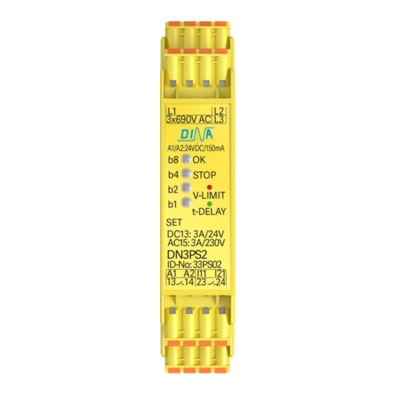
DINA DN3PS2 원본 사용 설명서 - 페이지 5
{카테고리_이름} DINA DN3PS2에 대한 원본 사용 설명서을 온라인으로 검색하거나 PDF를 다운로드하세요. DINA DN3PS2 12 페이지. Standstill monitoring for one and three phases motors without sensor system
DINA DN3PS2에 대해서도 마찬가지입니다: 원본 사용 설명서 (16 페이지)

DN3PS2
Original Betriebsanleitung
Gerätebeschreibung
• Die Eingangsklemmen L1, L2 und L3 müssen ständig
direkt mit dem zu überwachenden Antrieb verbunden
sein.
• Schaltkontakte dürfen diese Verbindung auch bei
abgeschaltetem Motor nicht unterbrechen.
• Zwischen den Klemmen L1, L2 und L3 und allen ande-
ren Klemmen besteht eine 4KV Potenzialtrennung.
• Die Ausgangskontakte 13-14 und 23-24 sind sichere
redundante NO Kontakte mit Stopp Kategorie 0 nach
EN 60204-1.
• Die Kontakte können zweikanalig parallel oder in Seri-
enschaltung sicherheitsgerichtet verwendet werden.
Funktion der Steuereingänge I11, I21
• Nur bei den Versionen 33PS02 bis 33PS05
• Die Stillstandsüberwachung ist inaktiv, wenn I11 und
I21 mit 24V DC verbunden sind. Siehe Tabelle 1: Aus-
wahl der Betriebsart
• Die Überwachung des Stillstands ist nur bei FA1 aktiv.
• Die Schutzeinrichtung ist dann bei Stillstand
entriegelt.
DN3PS2, ID-No.: 33PS08
• Diese Version hat 2 nicht sichere Status Halbleiterausgänge.
• Die Ausgänge O1, O2 sind vorgesehen, den Geräte- und
Betriebszustand an eine PLC zu übertragen.
• Die Eingänge I11, I21 sind nicht verfügbar.
Schaltzustand O1 und O2
Switching status O1 and O2
Betriebsspannung
Power supply
24V DC
3-Phasen-
L1
L2
Motor
L3
U1
V1
W1
M
3-phases
3
motor
U2 V2
W2
Betriebsspannung
Power supply
24V DC
L1
L2
L3
3-Phasen-
U1
V1
W1
M
Motor
3
3-phases
W2 U2
V2
motor
DN3PS2
O1
O2
Gerät
24V
24V
OK
0V
24V
0V
0V
Nicht OK
Anschluss Schema
A1
OK
b8
A2
Stop
b4
L1
b2
L2
b1
L3
SET
I11
I21
DN3PS2
A1
OK
b8
A2
Stop
b4
L1
b2
L2
b1
L3
SET
I11
I21
DN3PS2
Stand: 29.09.2017
Original instruction manual
• The input terminals L1, L2 and L3 have to be always
directly connected to the supply terminals of the mon-
itored drive.
• No switching contacts are allowed between L1, L2, L3
and the terminals of the drive.
• There is a 4KV electrical isolation between L1, l2, L3
and all other terminals of DN3PS2.
• The output contacts 13-14 and 23-24 are safe redun-
dant NO contacts stop category 0 according to
EN 60204-1.
• The contacts can be used as two-channel (parallel) or
serial safety circuit.
Function of the control inputs I11 and I21
• With versions 33PS02 to 33PS05 only
• The standstill monitoring is inactive if I11 and I21 are
wired to 24V DC. See table 1: Function modes selection
• The standstill monitoring is active, if the function
mode FA1 is selected.
• Safety cover is only unlocked at standstill.
DN3PS2, ID-No.: 33PS08
• This version has 2 not safe status semi-conductor outputs.
• These outputs (O1, O2) may be used to transfer the current
device- and operating status to a superordinate PLC.
• The control inputs I11 and I21 are not available.
Unit
Motor
OK
Stillstand
Bewegung
Not OK
Kein Einfluss
Betriebsspannung
Power supply
13
24V DC
3-Phasen-
14
L1
Motor
L2
L3
U1
3-phases
23
motor
24
W2 U2 V2
Betriebsspannung
1-Phasen-
Power supply
13
Motor
24V DC
14
L
1-phase
N
motor
23
24
Seite 5 von 12
Date: 2017-09-29
Unit description
Motor
A1
b8
A2
b4
Standstill
L1
b2
L2
Movement
b1
L3
No influence
O1
O2
DN3PS2
Connection schematic
A1
b8
A2
b4
L1
b2
L2
V1
b1
W1
L3
M
3
I11
I21
DN3PS2
A1
b8
A2
b4
L1
b2
L2
b1
L3
M
1
I11
I21
DN3PS2
Page 5 of 12
OK
13
Stop
14
23
SET
24
OK
13
Stop
14
23
SET
24
OK
13
Stop
14
23
SET
24
