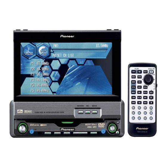
Pioneer AVH-P6600DVD 설치 매뉴얼 - 페이지 2
{카테고리_이름} Pioneer AVH-P6600DVD에 대한 설치 매뉴얼을 온라인으로 검색하거나 PDF를 다운로드하세요. Pioneer AVH-P6600DVD 9 페이지. 2004 mobile entertainment systems
Pioneer AVH-P6600DVD에 대해서도 마찬가지입니다: 소유자 매뉴얼 (34 페이지), 사용자 설명서 (24 페이지), 운영 매뉴얼 (4 페이지)

Connecting the Units
Connecting the Units
Connecting the power cord
15 cm
Jack for Wired Remote Control
(5-7/8 in.)
Please see the Instruction Manual for the
Wired Remote Control (sold separately).
IP-BUS input (Blue)
This product
Multi-CD player
(sold separately)
Violet
IP-BUS cable
Yellow/black
If you use a cellular telephone, connect it via the
Audio Mute lead on the cellular telephone. If not,
keep the Audio Mute lead free of any connections.
Red
Fuse resistor
To electric terminal controlled
by ignition switch (12 V DC)
ON/OFF.
Orange/white
Fuse resistor
To lighting switch terminal.
Yellow
Fuse holder
To terminal always supplied
with power regardless of
ignition switch position.
Black (ground)
To vehicle (metal) body.
Gray
White
+
+
Front speaker
Front speaker
≠
≠
Gray/black
White/black
Left
Violet
Green
+
+
Rear speaker
Rear speaker
≠
≠
Green/black
Violet/black
Antenna cable (supplied)
Black
2 m
(6 ft. 7 in.)
1.5 m
Antenna jack
Black
(4 ft. 11 in.)
21 pin cable (supplied)
Connection method
1.
Clamp the lead.
Note:
• The position of the parking brake switch depends
on the vehicle model. For details, consult the
vehicle Owner's Manual or dealer.
Light green
Used to detect the ON/OFF status of the parking brake.
This lead must be connected to the power supply side of the parking
brake switch.
Power supply side
Ground side
Blue/white
To system control terminal of the power amp
or Auto-antenna relay control terminal
(max. 300 mA 12 V DC).
With a 2 speaker system, do not connect anything
Right
to the speaker leads that are not connected to speakers.
When you connect separately sold multi-channel processor
(DEQ-P8000) to this unit, do not connect anything to the
speaker leads and system remote control (blue/white).
When connecting to separately sold power amp
Hide-away unit
Violet
26 pin cable (supplied)
This product
2. Clamp firmly with
needle-nosed
pliers.
Parking brake
switch
Fig. 2
Subwoofer output
or non fading output
(SUBWOOFER OUTPUT or
NON-FADING OUTPUT)
23 cm (9 in.)
Rear output
RCA cables
(REAR OUTPUT)
15 cm
(sold separately)
(5-7/8 in.)
Front output
(FRONT OUTPUT)
15 cm
(5-7/8 in.)
Blue/white
System remote control
To system control terminal of the power amp
or Auto-antenna relay control terminal
(max. 300 mA 12 V DC).
Left
When you connect separately sold
multi-channel processor (e.g. DEQ-P8000)
to this unit, do not connect anything to the
Front speaker
speaker leads and system remote control
(blue/white).
Note:
When you connect multi-channel processor to
Rear speaker
this unit, separately sold power amp must be
connected to multi-channel processor.
Note:
Change the initial setting of this product
Subwoofer
(refer to the Operation Manual).
The subwoofer output of this unit is monaural.
<ENGLISH>
<ENGLISH>
Power amp
(sold separately)
Power amp
(sold separately)
Power amp
(sold separately)
Right
+
+
Front speaker
≠
≠
+
+
Rear speaker
≠
≠
+
+
Subwoofer
≠
≠
Perform these connections when using
the optional amplifier.
Fig. 3
