Pioneer GM-X542 소유자 매뉴얼 - 페이지 2
{카테고리_이름} Pioneer GM-X542에 대한 소유자 매뉴얼을 온라인으로 검색하거나 PDF를 다운로드하세요. Pioneer GM-X542 8 페이지. Bridgeable power amplifier
Pioneer GM-X542에 대해서도 마찬가지입니다: 서비스 매뉴얼 (26 페이지)
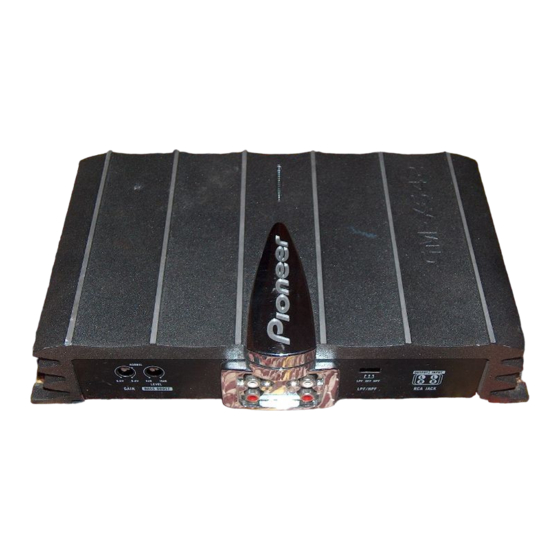
Setting the Unit
Gain Control
If the sound level is too low, even when
the volume of the car stereo used along
with this power amplifier is turned up,
turn gain control on the front of the
power amplifier clockwise. If the sound
distorts when the volume is turned up,
turn the gain control counter-clockwise.
• When using with an RCA equipped car
stereo (standard output of 500 mV), set to
the NORMAL position. When using with
an RCA equipped Pioneer car stereo with
max. output of 4 V or more, adjust level to
match the car stereo output level.
• If you hear too much noise when using the
speaker input terminals, turn the gain
control counter-clockwise.
Bass Boost Level Control
Bass Boost Level Control can boost the
level around 60 Hz from 0 to 18 dB.
• Bass Boost Level Control can be adjusted
only when the LPF/HPF select switch is set
to a position other than HPF.
Power Indicator
The power indicator lights when the
power is switched on.
LPF (Low-Pass Filter)/HPF (High-Pass Filter) Select Switch
Set the LPF/HPF select switch as follows according to the type of
speaker that is connected to the speaker output connector and the car
stereo system:
LPF/HPF Select
Audio frequency range
Speaker
Remarks
Switch
to be output
Type
LPF (left)
Very Low Frequency range
Subwoofer
Connect a subwoofer.
OFF (center)
Full range
Full range
HPF (right)
Low Frequency range to
Full range
Use if you want to cut the
High Frequency range
very low frequency range
because it is not necessary
for the speakers you are
using.
Connecting the Unit
CAUTION
• Disconnect the negative (–) terminal of the battery
• Make sure that wires will not interfere with mov-
to avoid the risk of short-circuit and damage to
ing parts of the vehicle, such as the gearshift,
the unit.
handbrake or seat sliding mechanism.
• Secure the wiring with cable clamps or adhesive
• Do not shorten any wires. Otherwise the protec-
tape. To protect the wiring, wrap adhesive tape
tion circuit may fail to work when it should.
around it where they lie against metal parts.
• Never feed power to other equipment by cutting
• Do not route wires where they will get hot, for
the insulation of the power supply wire to tap
example where the heater will blow over them. If
from the wire. The current capacity of the wire
the insulation heats up, it may become damaged,
will be exceeded, causing overheating.
resulting in a short-circuit through the vehicle
body.
To prevent damage
• Do not ground the speaker wire directly or con-
• Speakers to be connected to the amplifier should
nect a negative (–) lead wire for several speakers.
conform with the standards listed below. If they
• This unit is for vehicles with a 12-volt battery and
do not conform, they may catch fire, emit smoke
negative grounding. Before installing it in a recre-
or become damaged. The speaker impedance must
ational vehicle, truck or bus, check the battery
be 1 to 8 ohms for stereo connection, and 2 to 8
voltage.
ohms for monaural and other bridge connection.
• If the car stereo is kept on for a long time while
• Install and route the separately sold battery wire
the engine is at rest or idling, the battery may go
as far away as possible from the speaker wires.
dead. Turn the car stereo off when the engine is at
Install and route the separately sold battery wire,
rest or idling.
ground wire, speaker wires and the amplifier as
• If the system remote control wire of the amplifier
far away as possible from the antenna, antenna
is connected to the power terminal through the
cable and tuner.
ignition switch (12 V DC), the amplifier will
• Cords for this product and those for other prod-
always be on when the ignition is on— regardless
ucts may be different colors even if they have the
of whether the car stereo is on or off. Because of
same function. When connecting this product to
this, the battery could go dead if the engine is at
another product, refer to the supplied Installation
rest or idle.
manuals of both products and connect cords that
have the same function.
Speaker Channel
Speaker Type
Power
Subwoofer
Nominal input: Min. 60 W
Two-channel
Other than subwoofer
Max. input: Min. 100 W
Subwoofer
Nominal input: Min. 165 W
One-channel
Other than subwoofer
Max. input: Min. 300 W
Connection Diagram
Fuse (30 A)
Special red battery wire [RD-223] (sold separately).
After making all other connections at the amplifier,
Grommet
connect the battery wire terminal of the amplifier to
the positive (+) terminal of the battery.
Fuse (30 A)
Ground wire (black) [RD-223] (sold separately).
Connect to metal body or chassis.
RCA input
Amplifier with
RCA input jacks
Connecting wires with RCA
pin plugs (sold separately).
Car stereo with
RCA output jacks
External Output
Front side
RCA output jack
RCA input jack
Back side
Fuse (25 A)
Speaker terminal
System remote control wire (sold separately)
See the "Connecting the
Connect the male terminal of this wire to the system remote control
Speaker wires" section
terminal of the car stereo (SYSTEM REMOTE CONTROL). The
for speaker connection
female terminal can be connected to the auto-antenna relay control
instructions.
terminal. If the car stereo does not have a system remote control ter-
minal, connect the male terminal to the power terminal through the
ignition switch.