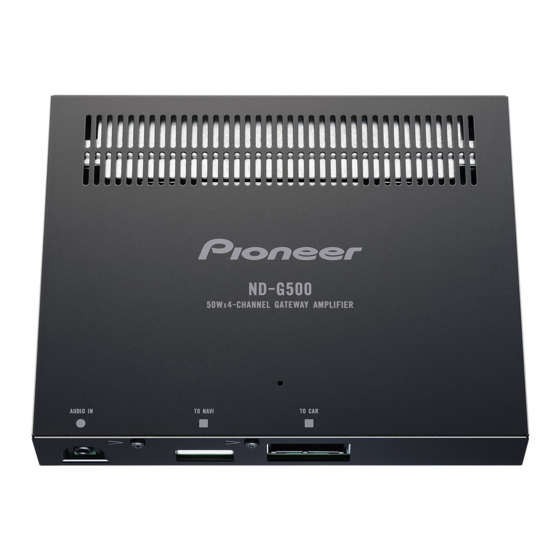
Pioneer ND-G500E5 서비스 매뉴얼 - 페이지 9
{카테고리_이름} Pioneer ND-G500E5에 대한 서비스 매뉴얼을 온라인으로 검색하거나 PDF를 다운로드하세요. Pioneer ND-G500E5 26 페이지. 4-channel gateway amplifier

5
4. BLOCK DIAGRAM
There is not information to be shown in this chapter.
5. DIAGNOSIS
5.1 TROUBLESHOOTING
Output audio from the Speaker is switched by "AMP control terminal" (Blue/white cable)
If the terminal signal is "L", the audio from Mini-plug (AVIC-F500BT) is selected.
If the terminal signal is "H", Car stereo audio is selected.
Please see following table for more detail.
Output Audio
AMP Control
from
terminal
(Blue/White)
Car stereo
H
AVIC-F500BT
L
5.2 CONNECTOR FUNCTION DESCRIPTION
AUDIO INPUT
6. SERVICE MODE
There is not information to be shown in this chapter.
5
6
Inside of a product
Q790 - Base
IC220, 250 2pin
(CONT2)
(CNT1)
L
L
H
H
1
1
5
2
1. FL-OUT
2. FL-IN
1. CNT
3. FL+OUT
2. NC
4. FL+IN
3. GND
5. FR-OUT
4. NC
6. FR-IN
5. 5V
7. FR+OUT
8. FR+IN
9. RR+OUT
10. RR+IN
ND-G500/XS/E5
6
7
IC220, 250 4pin
(CNT2)
L
L
19
20
11. RR-OUT
12. RR-IN
13. RL+OUT
14. RL+IN
15. RL-OUT
16. RL-IN
17. ACC
18. GND
19. BUP
20. GND
7
8
A
B
C
D
E
F
9
8
