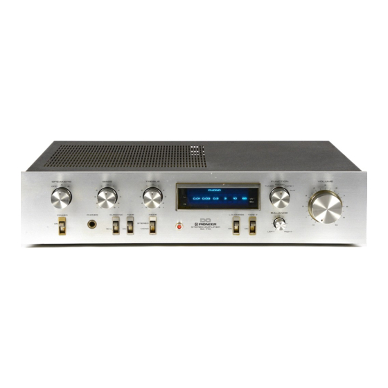
Pioneer SA-710 사용 설명서 - 페이지 6
{카테고리_이름} Pioneer SA-710에 대한 사용 설명서을 온라인으로 검색하거나 PDF를 다운로드하세요. Pioneer SA-710 13 페이지.
Pioneer SA-710에 대해서도 마찬가지입니다: 서비스 매뉴얼 (10 페이지)

CONNECTIONS
SPEAKER SYSTEM CONNECTIONS (Fig.
1)
The amplifier is
provided
with two
sets
of
SPEAKERS
output
terminals. Use
the
A
set when connecting
only
one set
of
speakers.
Viewed
from the
front, the
R
(right
channel)
SPEAKERS
terminals are
on the right
and
the
L
(left
channel)
SPEAKERS
terminals
are
on the
left.
Connect
the left
channel
speaker
to the
L terminals
and the
right
channel
speaker
to the
R
terminals.
The
red
L
and
R
SPEAKERS terminals
have
a plus
polarity
and
the
black
terminals
have
a
minus
polarity and the
speaker
systems
have also
the
same
dual
polarities.
When
connecting,
always
connect
minus
to
minus and plus
to
plus.
Cautions when connecting
the
speakers
1.
The
speaker
output
terminals have
polarities:
minus
(black) and plus
(red).
The input
jacks
on the
speakers
also
have
plus and
minus polarities. When connecting,
make
sure
that
these
polarities
are
aligned: plus
to
plus
and
minus
to
minus.
lf the left
and right
speaker
polarities
are misaligned,
the
reproduced sound
will
not
display
a
natural
stereo
effect.
2.
Use
speakers
with a
nominal
impedance ranging from
6
ohms
to
16 ohms.
3.
Never
use
the
speakers
with
the
speaker
output
terminals
shorted (minus and
plus jacks
connected)
since
this
may
damage
the
power
transistors in the amplifier.
Processing
and connecting
the
speaker
cords
(Fig.2)
1.
Cut
off
the
covering
of
the
speaker
cords
as
shown
in
Fig.2-e.
2.
lf
the
strands
at the tip of
the cord
are
pointing
in
all
directions,
twist
them
with
your thumb
and forefinger.
Otherwise some
of
the
strands
may
come
into
contact
with
other terminals
and cords, and
cause
a
short.
3.
Push
the
minus (black)
button
of
the
speaker
terminals
with your
finger
and insert the minus
speaker
lead
(black)
into
the hole
above
the
button.
The
lead
is
locked
into
position when
the button
is
released.
Check
that
the
lead
is
connected
firmly
(Fig.
z-@t'
4.
ln the
same
way,
connect
the
plus
speaker lead (red)
to
the
plus
terminal
(red).
5.
Check
that the core wires
of
the
speaker leads are
not
projecting
from the
terminals.
lf
they
should
come
into
contact, this
will
give
rise
to
a
shortcircuit.
SPEAKE
RS
terminals
Right
ch'annel
speaker system
Left
channel
speaker system
Fig.
1
I
o
@
@
Speaker
lead
wire
preparation
and
connection
Twist
the
strands
ry
tl
l_l
10mm
E
l
I
@
Connect
your
second
pair
of
speaker system.
Speaker cord
Fig.2
