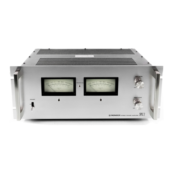
Pioneer SPEC-2 서비스 매뉴얼 - 페이지 7
{카테고리_이름} Pioneer SPEC-2에 대한 서비스 매뉴얼을 온라인으로 검색하거나 PDF를 다운로드하세요. Pioneer SPEC-2 50 페이지. Pioneer spec-2 stereo power amplifier operating instructions
Pioneer SPEC-2에 대해서도 마찬가지입니다: 사용 설명서 (17 페이지)

Current Limiter Circuit
The current limiter circuit, shown in Fig. 2, consists
of Q9 - qLz. If an overcurrent flows in the power
transistors, due to low load (less than 4S2) or load
shorting, this circuit
utilizes the voltage drop
produced in the power transistor emitter resistance
to limit the input voltage. Q9 - Q12 are normally
OFF, but if for some rea.son an overcurrent occurs
in the power transistors, the voltage drop compo-
nent of the power transistor emitter resistance
increases. This voltage is divided and used to bias
the bases of Q9 and Q11, switching them ON.
Q9 and Ql1
make Q10 and Q12 conductive,
limiting the signal voltages applied to the basis of
Q13 and Q14.
VR2 and VR3 in this circuit set the current limit-
ing value, while TH1 and TH2 are for temperature
compensation. RLG is a selector switch for chang-
ing the current limiting value at 4O load.
4 . 2 P E A K L E V E L M E T E R C I R C U I T
Logarithmic
indication
is required in order to
provide a broad indicating range in a single meter,
without the need for range selection by the user.
With respect to an 8O load, approximately 50dB
logarithmic
compression is performed to allow
meter indication in the range of 0.01 - 500W.
As shown in Fig. 3, the circuit is divided into
positive and negative sides. Each side consists of
logarithmic compression, peak value holding and
voltage to current converter circuits. In addition
there is a cunent resultant circuits, common to
both sides. The positive side circuit operation is
described here.
SPEC-p
A portion of the pov/er amplifier output signal is
compressed by the logarithmic compression circuit,
which utilizes the exponential function properties
of diodes. Figs. 4 and 5 illustrate the operating
principle
and input-output
response. The com-
pressed signal is then rectified and retained for a
suitable length of time by the peak holding circuit,
which employs a simple diode and capacitor con-
struction. Holding time is determined by ttre time
constant of C1 and R1.
The holding circuit voltage is then applied to the
voltage-current converter, where it is converted
into a current value and amplified. The current
afterwards passes through the current resultant
circuit and drives the meter.
The current resultant circuit applies the larger
current of the positive and negative sides to the
.meter for operation.
Fig. 4 Equivalent Circuit of the Logarithmic Compression
lC input voltage
Fig. 5 Input-output Response
I \
f
EL
+
Inprt voltagc(lC)
o
E
o
e
I
Yoltage current
Conv
e rter
e
4
=
e
e
€
o
E
PostTtvt
stDE
logarithmic
comp ress ion
Peak
r alue
ho ld ing
7
It0lltvt st0t
Fig. 3 Peak Level Meter Circuit
- P o s i t i v e
p e a k c u r r e n t
--' llegatiYe
peal current
