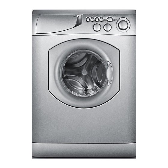
Ariston AW 125 수리 매뉴얼 - 페이지 7
{카테고리_이름} Ariston AW 125에 대한 수리 매뉴얼을 온라인으로 검색하거나 PDF를 다운로드하세요. Ariston AW 125 20 페이지. Washer / washer-dryer combo
Ariston AW 125에 대해서도 마찬가지입니다: 사용자 설명서 (23 페이지)

- 1. Table of Contents
- 2. Model & Serial Number Locations
- 3. Top Panel
- 4. Control Panel
- 5. Control Panel Components
- 6. Toe Kick & Drain Motor
- 7. Drum Boot
- 8. Door Switch
- 9. Water Valves
- 10. Heater Assembly (AWD 120 / 121 / 129 Only)
- 11. Pressure Switch
- 12. Rear Access Panel
- 13. Control Board
- 14. Main Motor
- 15. Fault Codes
- 16. Schematics
4. CONTROL PANEL COMPONENTS - Switches and Potentiometers
A
• The Control Panel has three main controls; Push Buttons (A), Knobs (B) and the Program Dial (C).
− To remove a Push Button (A), first mask the area to protect against damaging the Control Panel, then carefully insert a small
screwdriver between the bottom of the Button and the Control Panel (Fig. 4-2), now pry the Button out and off.
− To remove the Knobs (B) or the Program Dial (C), grasp the firmly and pull straight out toward you.
A
REPAIR MANUAL
B
C
A
B
Fig. 4-1
•
To remove either the Switches (A) or the Potentiometers
(B), first remove the Button and/or Knob. The Switch and
Potentiometers are held in place by four (4) positioning tabs
(Fig. 4-3). Using a small screwdriver press the tabs inward
then slide the Switch or Potentiometer out from the rear of
the Control Panel.
•
On both Fig. 4-4 Switch and Fig. 4-5 Potentiometer you can
see the positioning tabs.
TECH NOTE: The tabs on the Switches and Potentiometers
are very delicate and can easily snap off.
Use care when removing or replacing.
Fig. 4-3
AW 120 / AW 122 / AW 125
AWD 120 / AWD 121 / AWD 129
Fig. 4-4
Fig. 4-2
Fig. 4-5
Page: 4
