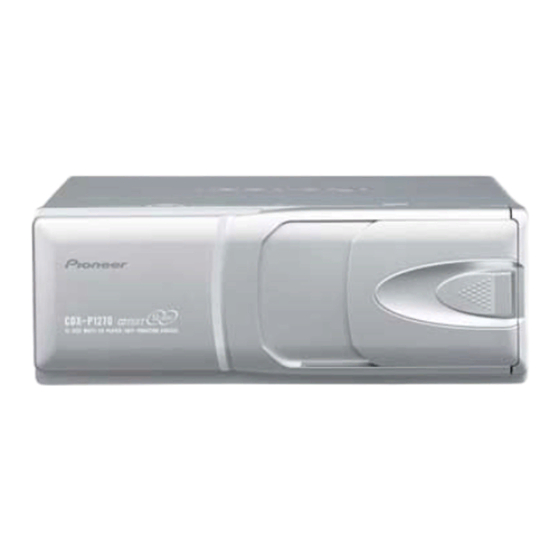
Pioneer CDX-P1270 서비스 수리 교육 - 페이지 45
{카테고리_이름} Pioneer CDX-P1270에 대한 서비스 수리 교육을 온라인으로 검색하거나 PDF를 다운로드하세요. Pioneer CDX-P1270 50 페이지. Multi-compact disc player
Pioneer CDX-P1270에 대해서도 마찬가지입니다: 소유자 매뉴얼 (4 페이지), 소유자 매뉴얼 (4 페이지), 소유자 매뉴얼 (4 페이지), 소유자 매뉴얼 (18 페이지)

- 1. Table of Contents
- 1. 1 Safety Information
- 2. 2 Exploded Views and Parts List
- 3. 3 Block Diagram and Schematic Diagram
- 3. CD Mechanism Module
- 4. 4 Pcb Connection Diagram
- 5. 5 Electrical Parts List
- 6. 6 Adjustment
- 7. 7 General Information
- 7. Diagnosis
- 7. Test Mode
- 7. Disassembly
- 7. Connector Function Description46
- 7. Operational Flow Chart
- 8. 8 Operations and Specifications
2. The slide is done in the direction of arrow5 and
remove the Door(B) while spread out the Door(A) in the
direction of arrow4. (Fig.8)
*) The illustration of the text for 12-Disc type but disas-
sembling method is the same for 6-Disc type.
- Removing the Pickup Unit
1. Insert the short pin from the pickup unit in the flexible PCB.
2. Remove the flexible PCB from the connector.
3. Remove the flexible card from the connector.
4. Remove the lead wires to which the spindle motor and carriage motor assy were soldered.
5. Remove the two screws and lift the mechanism PCB up as shown in the figure on the upper right.
At this time, make sure that the motor PCB and flexible relay card are not pulled excessively.
Short Pin
Flexible PCB
Mechanism PCB
6. Remove screw A and then remove the carriage motor assy, lighting conductor, feed screw holder, feed screw and
belt (see Fig.10).
7. Remove screw B on the main side and the pickup unit together with the guide shaft (see Fig.10).
Flexible card
Motor bracket
CRG motor
Feed screw
Guide shaft (main)
Pickup unit
Guide shaft (sub)
Door(A)
Door(B)
Erect
Motor PCB (handle
with care)
Flexible relay card (han-
dle with care)
Screw A
Lighting conductor
Screw A
Feed screw holder
Belt
Screw B
CDX-P1270
Fig.8
Fig.9
Fig.10
45
