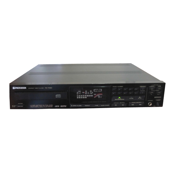
Pioneer PD-6050 서비스 매뉴얼 - 페이지 17
{카테고리_이름} Pioneer PD-6050에 대한 서비스 매뉴얼을 온라인으로 검색하거나 PDF를 다운로드하세요. Pioneer PD-6050 31 페이지.

The phase comparison output PDO which is input
from Pin 34 subjected to V-I conversion after having
its PWM carrier component eliminated at the Loop
Filter.
It is then added to the current from Pin 36
which is used for setting the free-run frequency in
order to control the VCO frequency.
The free-run
frequency of the VCO is approximately in inverse
proportion to the value of the resistor between Pins
36 and 37.
COMMAND
The input data used for operating this IC actually
consists of eight bits.
In the following description,
however, each command will be expressed using a
two-digit
hexadecimal
format
of
$XX
(with
X
ranging from 0 to F).
SOX ( @ SENS = "FZC")
This command is related to the control of the
focus servo. Its bit configuration is as follows:
D7
D6
D5
D4
D3
D2
Dl
DO
0
0
0
0
FS4 FS3 FS2 FS1
The four focus-related SWs are FS1 to FS4,
which respectively
correspond to DO to
D3
above.
$00 When FS1=0, Pin 13 is charged to: (22 fJLA
- 11 JUA) X 50 ktt
= 0.55V.
Moreover, if FS2 = 0, this voltage is trans-
mitted no further and the © output be-
comes 0 V.
$02 In the above status, only FS2 becomes 1.
At this time, a negative output is sent from
Pin 11.
This voltage level is stipulated as
follows:
(22 [JLA - 11 //A) X 50 ka
X Resistance
value between (Q), @/50 k£2 .....Equation (1)
$03 In the above status, FS1 = 1 so that the +22
/iA power supply is cut off.
Next, the Charge/Recharge circuit of CR is
formed, and the voltage of Pin 13 drops
with time as shown in Fig. 4-6 below.
Fig. 4-6.
Pin 13 Voltage when FS1 Changes from 0
to 1
This time constant is stipulated by C34 that is
externally connected to 50k 12.
The alternate issuing of $02 and $03 enables the
creation of the search voltage for focus.
(See Fig.
4-7)
Fig. 4-7.
Search Voltage Creation by $02 and $03
(Pin 11 Voltage)
1 7
