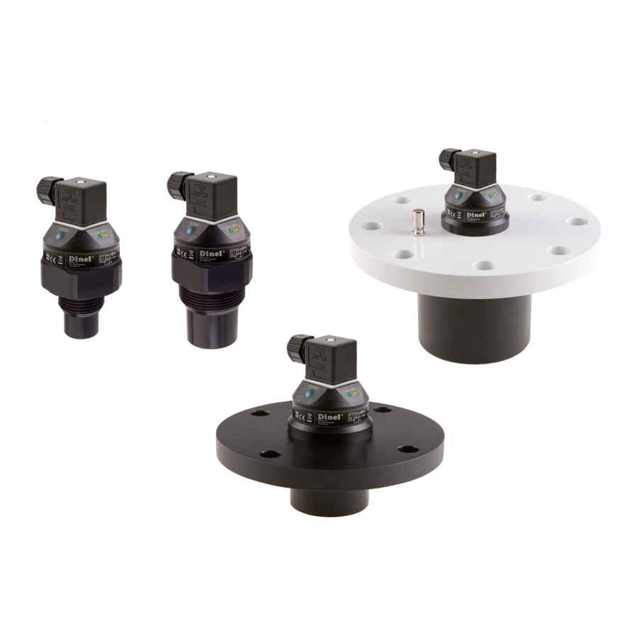
Dinel ULM-53 series 사용 설명서 - 페이지 9
{카테고리_이름} Dinel ULM-53 series에 대한 사용 설명서을 온라인으로 검색하거나 PDF를 다운로드하세요. Dinel ULM-53 series 20 페이지. Ultrasonic level meters
Dinel ULM-53 series에 대해서도 마찬가지입니다: 사용 설명서 (20 페이지), 매뉴얼 (8 페이지), 매뉴얼 (6 페이지)

E
LECTRICAL CONNECTION
The ultrasonic level meter is designed to be connected to supply unit or to controller through two
or three-wire cable with outer diameter 6 ÷ 8 mm (recommended cross section of cores 0.5 mm
to 0.75 mm
) by means of connector which is included in delivery. Connection diagram and inner
2
view of the connector as shown in
Fig. 14 and 15.
Make the electric connection in
voltage-free state.
Note: In case of strong electromag-
netic interferences (EMI), parallel
cable ducting with power lines, or
when cable length exceeds 30 m
we recommended to use shielded
cable.
WARNING:
With regard to possible occurrence
of electrostatic charge on non-
conductive parts of the level meter,
metallic fl anges of the ULM–53Xi–10
and 20 (for explosive areas) level me-
ters must be grounded with ground
terminal!
S
-
ET
UP ELEMENTS
button "DOWN"
– set-up mode access
– direct set-up to value 4 mA (0 V)
– decreasing of values by predefi ned pitch
button "UP"
– set-up mode access
– direct set-up to value 20 mA (10 V)
– increasing of values by predefi ned pitch
LED indicator "STATE"
– signalling of measuring mode
LED indicator "MENU"
– signalling of set-up mode access
© Dinel, s.r.o.
ULM–53
Fig. 14: Level meter connection diagram ("I" version) and the
inside of the connector socket
Fig. 15: Level meter connection diagram ("U" version) and the
inside of the connector socket
comments:
Connector
Safety screw
Ultrasonic transmitter
Fig. 16: Full view of ultrasonic level meter
0V (bu)
+U (bn)
0V (bu)
U
out
+U (bn)
bk – black
bn – brown
bu – blue
NC – not connected
Button "DOWN"
Button "UP"
LED indicator "MENU"
LED indicator "STATE"
2
(bk)
8
