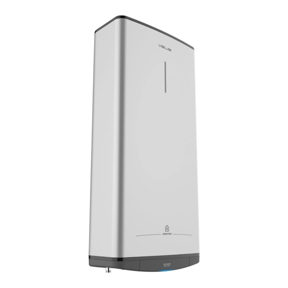
Ariston 3700712 조립 및 작동 지침 매뉴얼 - 페이지 36
{카테고리_이름} Ariston 3700712에 대한 조립 및 작동 지침 매뉴얼을 온라인으로 검색하거나 PDF를 다운로드하세요. Ariston 3700712 48 페이지.

In the case of walls made of bricks or perforated blocks, partition walls featuring limited static, or ma-
sonry different in some way from those stated, you first need to carry out a preliminary static check of
the supporting system. The wall-mounting fastening hooks must be designed to support a weight that is
three times higher than the weight of the water heater filled with water.
Fastening hooks with a diameter of at least 12 mm are recommended (Fig. 3)
We recommend installing the appliance (Fig. 1, Rif.A) as close as possible to the delivery points to
minimise heat loss along the pipes. Local regulations may provide for restrictions on installation in bath-
rooms; observe any regulatory minimum distances. To facilitate maintenance, make sure there is a clear-
ance of at least 50 cm inside the enclosure for access to the electrical equipment.
Multi-position installation
The product may be installed either vertically or horizontally (Fig. 2). To install it horizontally, rotate it
clockwise so that the water pipes are at the left (cold water pipe at the bottom). Any other installation
than that shown in (Fig. 2) is improper and prohibited.
HYDRAULIC CONNECTION
Connect the water heater's inlet and outlet with pipes or fittings that are able to withstand temperature in
excees of 90°C at a pressure exceeding that of the working pressure. Therefore, we advise against the
use of any materials which cannot resist such high temperatures.
The appliance must not be supplied with water of hardness less than 12°F, or with especially hard water
(greater than 25°F); we recommend installing a water softener, properly calibrated and controlled - do
not allow the residual hardness to fall below 15°F.
Screw a "T" piece union to the water inlet pipe with the blue collar. On one side of the "T" piece union,
screw a tap for draining the appliance that can only be opened with the use of a tool (Fig. 2, Rif.B).
On the other side of the "T" piece union screw the safety valve supplied (Fig. 2, Rif.A).
Safety group complies with the European standard EN 1487
Some countries may require the use of hydraulic special safety devices; the installer must check the
suitability of the safety device he tends to use.
Do not install any shut-off device (valve, cock, etc.) between the safety unit and the heater itself.
The appliance's drain outlet must be connected to a drain pipe of diameter at least equal to the of the
outlet itself, with a funnel to permit an air gap of at least 20 mm for visual inspection. Use a hose to con-
nect the safety group to the mains cold water supply; fit a cock if necessary (Fig.2, Rif.D).
In addition, a water discharge tube on the outlet (Fig.2, Rif.C) is necessary if the emptying tap is opened.
When installing the safety device, do not tighten it fully down, and do not tamper with its settings.
It is necessary to connect the drain, which must always be left exposed to the atmosphere, with a drain-
age pipe that is installed sloping downwards in a place with no ice. If the network pressure is closed
to the calibrated valve pressure, it will be necessary to apply a pressure reducer far away from the
appliance. To avoid any possible damage to the mixer units (taps or shower) it is necessary to drain any
impurities from the pipes
36 / EN
