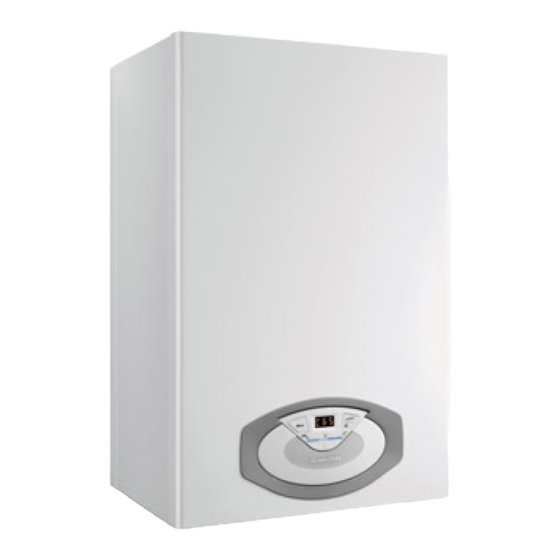
Ariston Clas 24 FF 설치 및 서비스 지침 - 페이지 16
{카테고리_이름} Ariston Clas 24 FF에 대한 설치 및 서비스 지침을 온라인으로 검색하거나 PDF를 다운로드하세요. Ariston Clas 24 FF 40 페이지. Wall-hung gas boiler type c
Ariston Clas 24 FF에 대해서도 마찬가지입니다: 사용자 설명서 (10 페이지)

installazione
Collegamento Periferiche
Per accedere alle connessioni delle periferiche procedere come segue:
- scollegare elettricamente la caldaia
- rimuovere il carter sganciandolo dal portastrumenti
- rimuovere il mantello frontale
- ruotare il pannello comandi tirandolo in avanti
- svitare le due viti del coperchio posteriore del portastrumenti
- sganciare la clip laterale destra, quella frontale destra e sollevare
lo sportellino
Si accede alla morsettiera per il collegamento di:
TA1 = Termostato ambiente Zona 1
TA2 = Termostato ambiente Zona 2
SE = Sonda Esterna
Si ha inoltre la possibilità di inserire delle schede opzionali per altri
accessori :
scheda bus per il collegamento di: Controllo Remoto,
Sensore Ambiente Modulante etc...
schede per la gestione di : multizone multitemperature,
solare etc...
Attenzione!
Per il collegamento ed il posizionamento dei cavi delle
periferiche
optionali
all'installazione delle periferiche stesse.
Collegamento termostato ambiente
- allentare il fermacavo con un cacciavite e inserire il cavo
proveniente dal termostato ambiente
- collegare i cavi ai morsetti seguendo come indicato in fi gura,
rimuovendo il ponticello
- assicurarsi che siano ben collegati e che non vengano messi in
trazione quando si chiude o si apre lo sportello portastrumenti
- richiudere lo sportellino, richiudere lo sportello portastrumenti e
il mantello frontale.
16
vedere
le
avvertenze
relative
installation
Peripheral unit connection
To access peripheral unit connections carry out the following steps:
- Disconnect the boiler from the power supply
- Remove the casing by unhooking it from the instrument panel
- Rotate the control panel while pulling it forwards
- Unscrew the two screws on the back cover of the instrument
panel
- Unhook the right side clip and the right front clip; then lift the fl ap
The terminal board (see fi gure) may be accessed in order to connect:
Room thermostat 1
Room thermostat 2
Outdoor sensor
Optional P.C.B.s can also be entered for further accessories:
BUS P.C.B.
OTHER PCB for solar installation, multizone etc....
Caution!
For the connection and positioning of the wires belong-
ing to optional peripheral units, please refer to the
advice relating to the installation of these units.
Room thermostat connection
- Introduce the thermostat wire
- Loosen the cable clamp using a screwdriver and insert the wires
leading from the room thermostat one at a time.
- Connect the wires to the terminals as indicated in the fi gure, removing
the jumper
- Make sure that they are well connected and that they are not subject
to traction when the control panel lid is opened or closed
- Close the fl ap again, then replace the control panel cover and the
front casing.
For the connection of the REMOCON
remote control Modulating room
sensor
