CALEFFI ThermoSetter 1164 A Series 설치, 시운전 및 서비스 지침 - 페이지 4
{카테고리_이름} CALEFFI ThermoSetter 1164 A Series에 대한 설치, 시운전 및 서비스 지침을 온라인으로 검색하거나 PDF를 다운로드하세요. CALEFFI ThermoSetter 1164 A Series 9 페이지. Recirculation thermal balancing valve
1
2
1
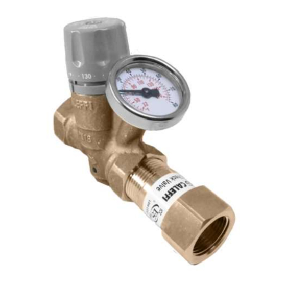
Thermostatic control,
1164xxA series
Function A
At the set temperature, the valve plug (1),
controlled by the thermostatic balancing cartridge
(2), gradually closes the outlet to the minimum
2
flow (3). The outlet never fully closes to always
allow a minimum flow for temperature sensing
and to prevent recirculation pump dead-heading.
If the temperature decreases, the outlet increases,
causing flow and thus temperature to increase
back to the set temperature as shown in curve
1. If temperature exceeds the set-point, the plug
stays in the minimum closed position as shown
in curve 2.
Installation
Before installing the ThermoSetter, flush the pipes to make sure that impurities in system
will not interfere with valve performance. Strainers of sufficient capacity at the inlet from the
water main are highly recommended. The ThermoSetter can be installed in any position,
vertical or horizontal, following the flow direction indicated by the arrow on the valve body.
The ThermoSetter must be installed according to the diagrams given in this manual. It must
be installed to allow free access to for checking on operation and maintenance procedures.
Scan to view
·
Installation Tip
2
3
3
1
3
Thermostatic control with check valve,
11614xAC series
G (gpm)
Cv
max
(2.1)
Cv
design
(0.69)
Cv
min
(0.35)
4
T
set
T (°F)