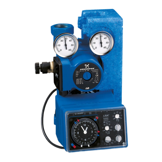
CALEFFI 152651 빠른 시작 매뉴얼 - 페이지 7
{카테고리_이름} CALEFFI 152651에 대한 빠른 시작 매뉴얼을 온라인으로 검색하거나 PDF를 다운로드하세요. CALEFFI 152651 8 페이지. Temperature regulating unit for heating and cooling

Example of safety thermostat application on system low
temperature branch circuit
Frost protection function
When the selector, point 6 on the front panel, is positioned
to
or
, there are two types of intervention:
a) If the flow temperature is below 7°C, the controller activates the
operation of the unit until a flow temperature of 20°C is reached.
When this value is reached, it will return to the inactive status.
b) If the outside temperature is below 5°C (+2 -0), the controller
keeps the pump running.
Anti-seize function
If the pump remains inactive for twenty four hours, the following
program automatically comes into operation, with:
mixing valve open for 30 seconds,
mixing valve closed for 30 seconds,
pump ON for 60 seconds.
When this function is operating, it cannot be interrupted.
Manual control
To carry out adjustment:
- Remove the servomotor fixing screws.
- Lift the servomotor. This gives access
to the control knob.
Refer to the information given on
the knob itself.
Options
Room thermostat, code 151000.
The regulating unit can be
supplemented
with
a
thermostat, able to adjust the
value of the flow temperature
according to the actual room
temperature. This configuration
makes it possible to take account
of gratuitous heat gains, by
refining the value of the flow
temperature, with optimum results
in terms of comfort and energy
saving. In cooling conditions, the
setting on the thermostat should
be increased by 2°C.
CALEFFI
24
18
22
12
60
50
70
40
80
9
3
WATCH
30
90
-25%
6
-50%
room
18
CALEFFI
Operation of the room thermostat
The room thermostat makes it possible to optimise the operation of
the system, as it modifies the regulating curve automatically.
Depending on the time periods for comfort and set-back selected
on the clock and the room temperature setting, it will read the actual
room temperature. On the basis of this parameter, it will make any
necessary modification to the characteristic curve (A) for the
purpose of accelerating operation and preventing excessive
heating or cooling of the room.
The difference between the actual room temperature measured by
the thermostat and the set temperature produces an amplified
26
28
30
32
34
effect in relation to that produced by a similar variation in the
+25%
0
outside temperature.
A difference of 1°C in the room temperature causes a move of the
characterisitc curve equal to 7°C of the outside temperature, with
the corresponding variation in flow temperature.
For example, if T
difference of 1°C will cause a movement of the characteristic curve
of 7°C towards the left (B). The flow temperature will consequently
be raised. In the case of a negative difference, the movement will
take place on the curve C.
This behaviour is applicable for a maximum difference of 3°C in the
room temperature.
In addition, the maximum temperature limit set at item 6 on the PCB
remains active.
In the set-back band, the set room temperature is automatically
reduced by 2°C, thus defining T
This reduction will cause a move to the right of the characteristic
curve, equating to 14°C of the outside temperature (D), with a
corresponding variation in flow temperature.
Whenever the measured room temperature falls below T
the initial characteristic curve (A) will be restored with the set-back
correction set at point 12 on the front panel.
Curve with room thermostat regulation
60
55
50
45
40
35
30
25
20
15
10
25
Room thermostat electrical connection
Install the room thermostat and connect by sheathed 2-core cable
(2x0,75) to the terminal strip of the regulator PCB, as shown in the
diagram below.
20
22
16
24
WARNING - if the connecting cable between the thermostat
and the control unit is not sheathed, it must be run in its own
ducting.
The maximum length is 150 m.
set = 20°C and T
room
set set-back
B
A
C
D
20
15
10
5
TA1
TA
Room thermostat
measured = 19°C, than the
room
.
set set-back
0
-5
-10
-15
T
(°C)
OUTSIDE
TA 1
TA
,
