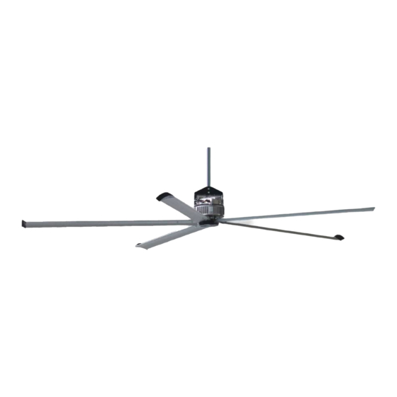
aerauliqa QHS Series 특정 매뉴얼 - 페이지 15
{카테고리_이름} aerauliqa QHS Series에 대한 특정 매뉴얼을 온라인으로 검색하거나 PDF를 다운로드하세요. aerauliqa QHS Series 20 페이지. Ceiling high volume low speed fan

WARNING: regardless of the control system in place (potentiometer or ModBus), it's strongly recommended to
wire the ModBus communication line and make it accessible from ground level, in order to ease troubleshooting
via ModBus anytime after the installation.
9. CLEANING
The unit (IP65) can be washed with water jets. In this case it is recommended to drill a hole under the plastic cover for water drainage.
10. TROUBLESHOOTING (ModBus)
10.1 Connection parameters
10.2 ModBus Registers - Input Register
These registers are READ-ONLY, and can be read using the function 04 READ INPUT REGISTERS.
Register
Description
Address
3
Measured speed
10
Alarm 1
17
Alarm 2
33
Minutes Time Counter
34
Hours Time Counter
CTRL-A (ACCESSORY ON REQUEST)
4-core power cable
BROWN
6-core control cable
YELLOW
GREEN
230V
WHITE
GREY
PINK
Protocol
Baud Rate (bps)
Data bits
Parity bits
Stop bits
HVLS Slave Address
Dimension
Data
U.M. (data on
(Word)
Type
1
ushort
1
ushort
1
ushort
1
ushort
1
ushort
EXTERNAL CONTACTOR
(NOT SUPPLIED)
YELLOW-GREEN
BROWN
BLACK
GREY
BOBINA
230V
CTRL - A
POT.
+
U
-
BIPOLAR
SWITCH
MODBUS B
MODBUS A
X
MODBUS/RTU over RS485
9600
8
none
2
1
Register value → Real value
the register)
0.1rpm
-
-
Minutes
Start to Count when Motoinverter is On.
Hours
Start to Count when Motoinverter is On.
15
L1
400 Vac
3 ph.
L2
50/60 Hz
L3
Example
490 → 49rpm
See table (§ 10.3)
See table (§ 10.3)
23 → 23 Minutes
Store lifetime data
1234 → 1234 Hours
Store lifetime data
