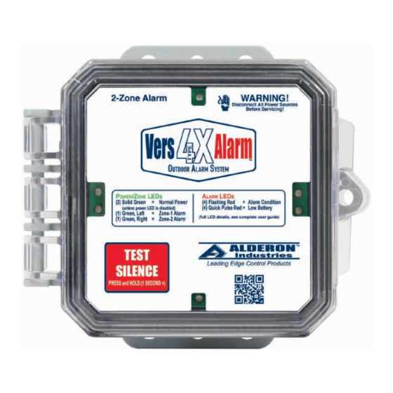
Alderon Industries VersAlarm 4X 운영, 유지보수 및 설치 매뉴얼 - 페이지 2
{카테고리_이름} Alderon Industries VersAlarm 4X에 대한 운영, 유지보수 및 설치 매뉴얼을 온라인으로 검색하거나 PDF를 다운로드하세요. Alderon Industries VersAlarm 4X 3 페이지. 2-zone outdoor
Alderon Industries VersAlarm 4X에 대해서도 마찬가지입니다: 운영, 유지보수 및 설치 매뉴얼 (6 페이지)

VersAlarm 4X
Indoor / Outdoor Alarm System
(auxiliary contact models)
Operation, Maintenance and Installation Manual
Installation
1. Determine mounting location for the VersAlarm™ 4X. Mount the unit using four #8 x 1.25" self tapping screws
(not included) (Fig. 1). Mounting brackets are 3.125" x 5.625" (Width x Height).
2. Drill holes for conduit connections, see Figure 2 for recommended hole locations on the enclosure. Attach
conduit per National Electrical Code.
3. Bring power wires through the conduit into the unit and connect to the terminal block (Fig. 3). Connect L1 to
TB1, N to TB2 and G to TB3. Make sure the power is on a separate circuit breaker from any other device to
maintain power integrity.
4. Bring "signaling device" wires (such as a float or pressure switch, etc.) through the conduit and connect to the
terminal block (Fig. 3). Connect to TB4 and TB5.
installation instructions for proper installation. Connect only with UL or CSA listed switches rated 1 amp at 120
VAC minimum.
5. Refer to the included schematic for additional wiring information.
Caution!
6.
- When installing wires, route all wires away from sharp objects and internal components. After all
wires are installed, seal all conduits, per National Electrical Code, that come from sources containing corrosive
gases. Failure to do so will cause premature failure and void warranty.
7. Reinstall the enclosure cover and carefully tighten the four screws.
(Fig. 1)
Mounting Holes (2)
Mounting Holes (2)
Testing
1. Turn on power and then press the "Test" button, located on the left side of the unit (Fig. 2). Once the "Test"
button is pressed, the buzzer should annunciate and beacon should illuminate. While pressing the "Test" button,
press the "Silence" button and the buzzer should silence. Let go of the "Test" button and repeat the sequence
several times to ensure the system is working properly.
2. Test the system similar to Step 1, but by activating the "signaling device". The buzzer should annunicate and
the beacon should illuminate.
3. Test product weekly to ensure system integrity.
Alarm Systems
Control Panels
PO Box 827 Hawley, MN 56549 (218) 483-3034 Fax (218) 483-3036 www.alderonind.com
Caution!
(Fig. 2)
Test
Button
Silence
Button
Recommended
Conduit Hole Locations
Float Switches
Leak Detection Systems
- When installing the "signaling device", refer to its
Terminal Block (TB) 1 2
Beacon
Buzzer
CAUTION!
and float as shown (Fig. 3) will cause
catastrophic circuit board damage.
Do not exceed 8 in. lbs. torque when
tightening screw terminals.
Wire Range: 12-24 AWG
QSG00269_Rev01
(Fig. 3)
3 4 5
L1 N
G
(120 VAC 50/60 Hz)
Signaling
Device
(Float Switch)
- Failure to connect power in
Page 2 of 2
