Alderon Industries VersAlarm I/O VLIO-0001 사용자 설명서 - 페이지 7
{카테고리_이름} Alderon Industries VersAlarm I/O VLIO-0001에 대한 사용자 설명서을 온라인으로 검색하거나 PDF를 다운로드하세요. Alderon Industries VersAlarm I/O VLIO-0001 20 페이지. Indoor/outdoor alarm panel
Alderon Industries VersAlarm I/O VLIO-0001에 대해서도 마찬가지입니다: 빠른 시작 매뉴얼 (2 페이지)
Wall Mounting Enclosure (continued)
STEP 3: MOUNT ENCLOSURE
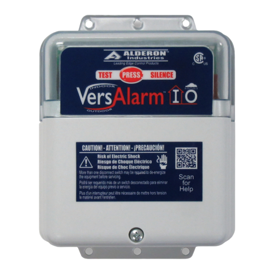
Determine the mounting location for the VersAlarm™ I/O.
Hold the alarm up to the desired mounting location, mark the
drill hole locations. Once marked, drill pilot holes for screws
(not included) and use wall mount anchors (not included) if
necessary. Place enclosure in mounting location, adjust until
the pilot holes are lined up with the enclosure and fasten screws
to secure the alarm panel in place.
Wiring
STEP 1: WIRING
The wiring diagram shows six terminals on the terminal block
that consists of three pairs of connections.
1) Starting from the left, the first pair of terminals (1 and 2)
are for the sensor connections. The sensor is typically a
float switch, but most digital switch sensors will work with
the sensor input.
2) The second pair of terminals (3 and 4) are for the auxiliary
contacts. This connection can be used on most digital
peripheral alarm monitors or extensions.
3) The third pair of terminals (5 and 6) are for the power
mains. The line connection (L1) is installed in terminal 5
and the neutral (N) is installed in terminal 6.
4) NEVER leave ground wire exposed inside the panel, use
provided Wago connector for ground termination. See
step 2 for installing wire into Wago connector.
VersAlarm™ I/O | USER GUIDE
Alderon Industries™ - Leading Edge Control Products | 7
SENSOR
AUX
POWER
1 2
3 4 5 6
WAGO