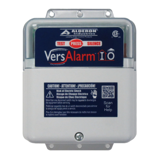
Alderon Industries VersAlarm VLIO-0004 빠른 시작 매뉴얼
{카테고리_이름} Alderon Industries VersAlarm VLIO-0004에 대한 빠른 시작 매뉴얼을 온라인으로 검색하거나 PDF를 다운로드하세요. Alderon Industries VersAlarm VLIO-0004 2 페이지. Indoor/outdoor alarm panel

VersAlarm
Indoor/Outdoor Alarm Panel | Model: VLIO-0004
QUICK START GUIDE
Step 2: Installing Conduit / Fittings
Using the pre-marked center hole
locations (2A), mark and drill out
on the bottom of the enclosure.
The size(s) will depend on desired
conduit fitting (maximum 0.75").
Place the conduit fitting (2B) in
the drilled out hole and make sure
it's secured. Then, install conduit
(2C) into the fitting.
Note: Seal all conduits to prevent moisture and
gases from entering the enclosure per local codes.
CAUTION: Nonmetallic enclosure does not provide
proper grounding between conduit connections. Use
grounding bushings and jumper wires.
Step 3: Mount Enclosure
Determine the mounting location
for the VersAlarm™ I/O. Hold the
alarm up to the desired mounting
location, mark the drill hole
locations. Once marked, drill pilot
holes for screws (not included)
and use wall mount anchors (not
included) if necessary. Place
enclosure in mounting location,
adjust until the pilot holes are
lined up with the enclosure and
fasten screws to secure the alarm
panel in place.
I/O
™
2A
2B
2C
Safety Guidelines
Before proceeding with the installation or operation of this product,
read all instructions thoroughly, as well as complying with all federal,
state and local codes, regulations, and practices. This product must
be installed by qualified personnel familiar with all applicable local
electrical and mechanical codes. Refer to the National Electrical Code
(NFPA 70). Failure to properly install and test this product can result in
personal injury or equipment malfunction.
Step 1: Remove Bottom Cover
Remove the bottom enclosure cover screw, slide directly downward
(1A) and then pull directly away (1B).
1A
1B
Step 4: Wiring
The diagram below shows the six terminals on the terminal block that
consists of three pairs of connections.
1) Install the sensor to terminals 1 and 2.
2) Installing an auxiliary device to terminals 3 and 4 is optional.
3) Install incoming power to terminals 5 and 6, first line (L1) in
terminal 5 and second line (L2) in terminal 6.
4) NEVER leave ground wire exposed inside the panel, use provided
Wago connector for wire termination.
SENSOR
1
2
3
Installing Wire into Wago Connector:
1) Lift tab(s) upward.
2) Insert wire(s) into slot.
3) Press tab(s) downward.
4) Make sure wire(s) are secured.
WARNING
AUX
POWER
4
5
6
TO OPEN
TO CLOSE
WAGO
WAGO
