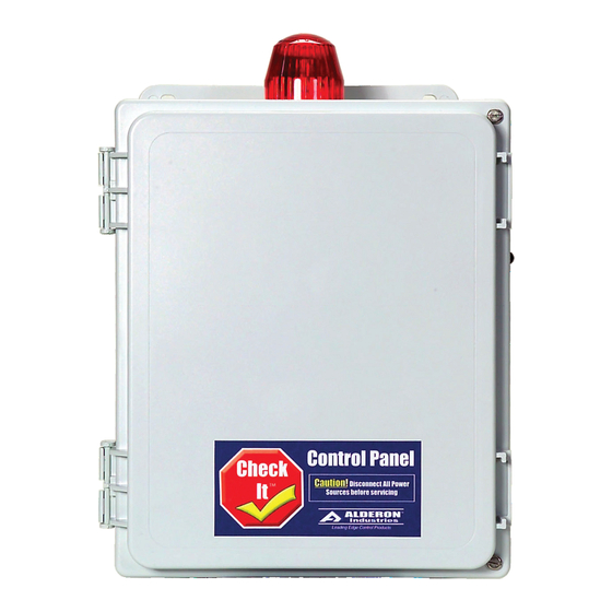
Alderon Industries Check It Series 운영, 유지보수 및 설치 매뉴얼 - 페이지 4
{카테고리_이름} Alderon Industries Check It Series에 대한 운영, 유지보수 및 설치 매뉴얼을 온라인으로 검색하거나 PDF를 다운로드하세요. Alderon Industries Check It Series 4 페이지.

Check It
1 Phase Duplex
Operation, Maintenance and Installation Manual
Installation of the Control Panel:
1
.
Determine mounting location for the control
panel. Attach the 4 mounting feet to the control
panel enclosure. If splicing is required between the
level switches and the panel, we recommend an
Alderon Junction box. CAUTION! Use conduit
sealant and waterproof wire nuts for connections.
Make sure all connections are water tight.
2.
Determine conduit entrance locations on
control panel and install per local codes. Check
schematic and determine number of power sources
required. Use conduit sealant on all conduits to
prevent moisture and gases from entering control
panel.
3.
Connect control/alarm and pump power
conductors to the proper terminals. The schematic
and terminal blocks will be labeled for proper
connection.
4.
Verify correct panel operation after installa-
tion of panel, power and level switches are complete.
Incoming Power Configurations:
The Check It series control panels may be ordered with or without circuit breakers. In either case the
incoming power for each pump is separated at the incoming power terminal block. For panels without
circuit breakers individual branch circuit breakers must be wired into the control panel. For panels with
circuit breakers either one or two power sources may be wired to the control panel. Illustration below
shows how to connect power for one or two incoming pump power sources.
1 Incoming Power Circuit
Install jumper wires:
12 AWG for pumps up to 25 Amps
10 AWG for pumps up to 30 amps
Incoming Power
for both pumps
Alarm Systems
Control Panels
PO Box 827 Hawley, MN 56549 (218) 483-3034 Fax (218) 483-3036 www.alderonind.com
Panel
™
Float Switches
Mounting Level Switches:
Float switches are most commonly used, but the
Check It series control panels can be used with any
dry contact type level or pressure switch. Illustra-
tions show float switches and installed for pump
down applications. Reverse float order for Pump Up
applications. Refer to float switch instuctions for
mounting of pipe clamp or weighted floats.
Lag Pump Start
& Alarm Float
Lead Pump
Start Float
Stop Float
Fig. #A
3 float configuration
2 Incoming Power Circuits
Pump 1
Incoming Power
Pump 2
Incoming Power
Leak Detection Systems
Alarm Float
Lag Pump
Start Float
Lead Pump
Start Float
Stop Float
Fig. #B
4 float configuration
P/N: 100836
Page 4 of 4
