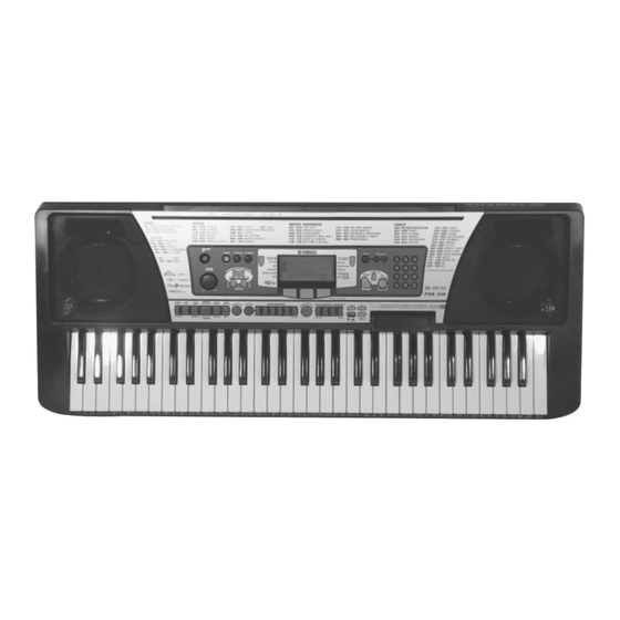
Yamaha PortaTone PSR-350 서비스 매뉴얼 - 페이지 11
{카테고리_이름} Yamaha PortaTone PSR-350에 대한 서비스 매뉴얼을 온라인으로 검색하거나 PDF를 다운로드하세요. Yamaha PortaTone PSR-350 34 페이지.

6.
PN 1 Circuit Board
(Time required : About 15 min.)
6-1.
Remove the lower case assembly. (See procedure 1)
6-2.
Remove the DM circuit board and the shield box
U and L. (See procedure 3)
6-3.
Remove the floppy disk drive assembly. (See
procedure 4)
6-4.
Remove the six (6) screws marked [260C]. The
PN 1 circuit board can then be removed. (Fig. 6)
7.
PN 2 Circuit Board
(Time required : About 20 min.)
7-1.
Remove the lower case assembly. (See procedure 1)
7-2.
Remove the DM circuit board and the shield box
U and L. (See procedure 3)
7-3.
Remove the floppy disk drive assembly. (See
procedure 4)
7-4.
Remove the AM circuit board. (See procedure 5)
7-5.
Remove the ten (10) screws marked [260D]. The
PN 2 circuit board can then be removed. (Fig. 6)
8.
PN 3 Circuit Board
(Time required : About 8 min.)
8-1.
Remove the lower case assembly. (See procedure 1)
8-2.
Remove the six (6) screws marked [260E]. The
PN 3 circuit board can then be removed. (Fig. 6)
9.
PN 4 Circuit Board
(Time required : About 10 min.)
9-1.
Remove the lower case assembly. (See procedure 1)
9-2.
Remove the AM circuit board. (See procedure 5)
9-3.
Remove the four (4) screws marked [260F]. The
PN 4 circuit board can then be removed. (Fig. 6)
PN1
[260C]x6
[260] : Bind Head Tapping Screw-P
[L50] : Bind Head Tapping Screw-P
[260F]x4
LCD
[260I]x4
[L50]x8
LCD Unit
PN2
[260D]x10
3.0X8
3.0X8
(Fig. 6)
10.
PW Circuit Board
(Time required : About 5 min.)
10-1.
Remove the lower case assembly. (See procedure 1)
10-2.
Remove the two (2) screws marked [260G]. The
PW circuit board can then be removed. (Fig. 6)
11.
VR Circuit Board
(Time required : About 10 min.)
11-1.
Remove the lower case assembly. (See procedure 1)
11-2.
Remove the AM circuit board. (See procedure 5)
11-3.
Remove the volume knob from the control panel
side. (Fig. 7)
11-4.
Remove the three (3) screws marked [260H]. The
VR circuit board can then be removed. (Fig. 6)
12.
LCD Unit (LCD Circuit Board, Back Light
Assembly and LCD)
(Time required : About 20 min.)
12-1.
Remove the lower case assembly. (See procedure 1)
12-2.
Remove the DM circuit board and the shield box
U and L. (See procedure 3)
12-3.
Remove the AM circuit board. (See procedure 5)
12-4.
Remove the four (4) screws marked [260I]. The
LCD unit can then be removed. (Fig. 6)
12-5.
Remove the eight (8) screws marked [L50]. The
LCD circuit board can then be removed. (Fig. 6)
*
When you install the LCD circuit board, tighten the screws
from No.1 to No. 8 in order as shown in Figure 6-1.
[260G]x2
PN4
PW
VR
[260E]x6
PN3
[260H]x3
MFZN2Y
(EP600280)
MFZN2Y
(EP600280)
Volume Knob
(Fig. 7)
3
4
5
6
LCD
1
7
8
2
(Fig. 6-1)
PSR-350
11
