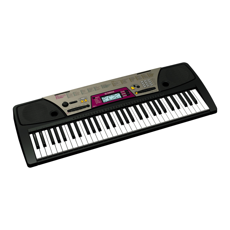
Yamaha Portatone PSR-172 서비스 매뉴얼 - 페이지 8
{카테고리_이름} Yamaha Portatone PSR-172에 대한 서비스 매뉴얼을 온라인으로 검색하거나 PDF를 다운로드하세요. Yamaha Portatone PSR-172 17 페이지.

H
I
PSR-172
3
OVERALL CIRCUIT DIAGRAM
TR101, R119, R120 and IC002 (DM-LCD) have been modified.
4
VR
MASTER
VOLUME
5
6
7
:
Mylar Capacitor
8
:
Ceramic Capacitor
: Semiconductive Ceramic Capacitor
: Metal Oxide Film Resistor
Note : See parts list for details of circuit board component parts.
8
J
PN-AM
1/2
POWER AMP
REGULATOR
+5V
(Modifying part)
STANDBY/ON
2SB1135 or 1269
*1: The fuse is soldered.
DM-LCD, PN-AM, VR : 28CC1-8819402
MK-L, MK-H : 28CC1-8819596
WARNING
Components having special characteristics are marked Z and must
be replaced with parts having specification equal to those originally
installed.
K
PHONES/
OUTPUT
SPEAKER
L
DC IN 12V
*1
7
L
