Yamaha R-N500 소유자 매뉴얼 - 페이지 9
{카테고리_이름} Yamaha R-N500에 대한 소유자 매뉴얼을 온라인으로 검색하거나 PDF를 다운로드하세요. Yamaha R-N500 20 페이지.
Yamaha R-N500에 대해서도 마찬가지입니다: 펌웨어 업데이트 (4 페이지)
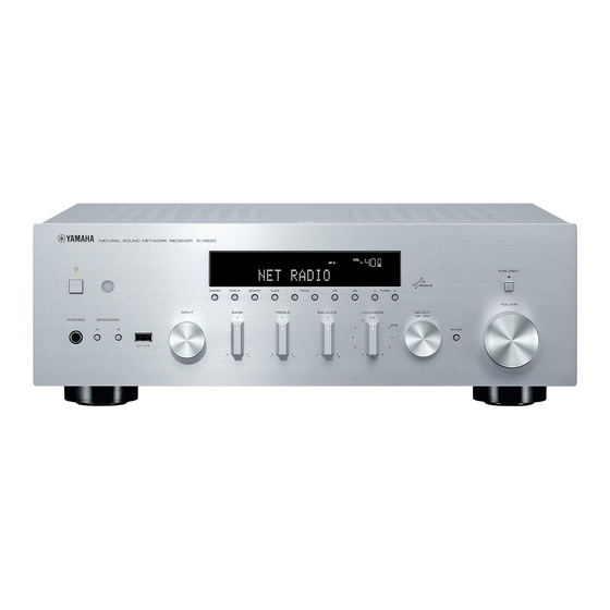
Rear panel
1
2 3
:
A
1 PHONO jacks
For connecting to a turntable (p.10).
2 OPTICAL 1-2 jacks
For connecting to audio components equipped with
optical digital output (p.10).
3 ANTENNA terminals
For connecting to FM and AM antennas (p.12).
4 COAXIAL 1-2 jacks
For connecting to audio components equipped with a
coaxial digital output (p.10).
5 SPEAKERS terminals
Used to connect speakers (p.11).
6 NETWORK jack
For connecting to a network (p.13).
7 DC OUT jack
For supplying power to a Yamaha AV accessory. For
details on connections, refer to the instruction manual of
the AV accessory.
8 VOLTAGE SELECTOR (General model only)
Selects the switch position according to your local voltage
(p.14).
9 Power cable
For connecting to an AC wall outlet (p.14).
0 LINE 1-3 jacks
For connecting to analog audio components (p.10).
A CD jacks
For connecting to a CD player (p.10).
B SUBWOOFER PRE OUT jack
For connecting to a subwoofer with built-in amplifier
(p.10).
4
5
B
C
6
7
C REMOTE IN/OUT jacks
When you have another Yamaha component supporting
remote connection, as this unit does, an infrared
transmitter is not necessary. You can transmit remote
signals by connecting an infrared receiver and the
REMOTE IN jack of the other component to the
REMOTE IN/OUT jacks of this unit, using cables with
monaural miniplugs.
Up to six Yamaha components (including this unit) can be
connected.
Rear panel of R-N500
Infrared receiver
Remote control
Controls and functions
Controls and functions
8
9
(General model)
REMOTE
IN
OUT
Yamaha component
(up to six components
including this unit)
7
En