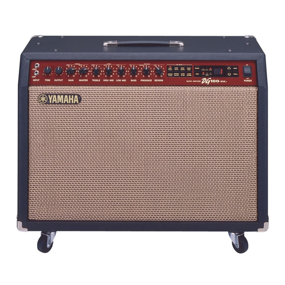
Yamaha DG100-212 서비스 매뉴얼 - 페이지 7
{카테고리_이름} Yamaha DG100-212에 대한 서비스 매뉴얼을 온라인으로 검색하거나 PDF를 다운로드하세요. Yamaha DG100-212 42 페이지. Yamaha guitar amplifier owner's manual
Yamaha DG100-212에 대해서도 마찬가지입니다: 소유자 매뉴얼 (32 페이지)

3.
Front Panel Assembly
3-1 Remove the pre-main unit. (See Procedure 1)
3-2 Remove the five (5) screws marked [30B]. The
front panel assembly can then be removed. (Fig. 3)
4.
ANR Circuit Board
4-1 Remove the pre-main unit. (See Procedure 1)
4-2 Remove the screw marked [50], the two (2)
screws marked [170], the two (2) knobs marked
[60] and the four (4) hexagonal nuts marked [A].
The ANR circuit board assembly can then be
removed. (Fig. 3)
4-3 Remove the two (2) screws marked [40d]. The
ANR circuit board can then be removed from the
ANR circuit board assembly. (Fig. 3)
5.
DM Circuit Board
5-1 Remove the pre-main unit. (See Procedure 1)
5-2 Remove the ANR circuit board. (See Procedure 4)
5-3 Remove the two (2) screws marked [40] and the
six (6) screws marked [30C]. The DM circuit
board can then be removed. (Fig. 3)
6.
Main (1/5-2/5) Circuit Board
6-1 Remove the pre-main unit. (See Procedure 1)
6-2 Each circuit board can then be removed in its
manner as below.
Main 1/5 Circuit Board
Remove the six (6) screws marked [60B]. The
main 1/5 circuit board can then removed. (Fig. 3)
Main 2/5 Circuit Board
Remove the screw marked [150A]. The main 2/5
circuit board can then removed. (Fig. 3)
Main 3/5 Circuit Board
Remove the screw marked [150B]. The main 3/5
circuit board can then removed. (Fig. 3)
Main 4/5 Circuit Board
Remove the screw marked [150C]. The main 4/5
circuit board can then removed. (Fig. 3)
Main 5/5 Circuit Board
Remove the screw marked [150D]. The main 5/5
circuit board can then removed. (Fig. 3)
7.
Power Transformer
7-1 Remove the pre-main unit. (See Procedure 1)
7-2 Remove the four (4) screws marked [80A]. The
Transformer can then be removed. (Fig. 3)
[A]
[60]
[170]
[50]
[60]
[A]
ANR
Sub angle
[40d]
[40]
MAIN 5/5 MAIN 4/5
MAIN 3/5
[30C] x 6
DM
[150D]
[150C] [150B] [150A]
Front panel assembly
[30B]:
Bind Head Tapping Screw-A4.0 x 8 MFZN2BL (VP156800)
[30C]:
Bind Head Tapping Screw-B 3.0 x 6 MFZN2BL (EP600230)
[40]:
Bind Head Tapping Screw-B 3.0 x 8 MFZN2BL (EP600190)
[40d]:
Pan Head Screw SP3.0 x 8 MFZN2Y (EK400500)
[50]:
Bind Head Screw A3.0 x 8 MFZN2BL (VP156700)
[60B]:
Bind Head Tapping Screw-B 3.0 x 6 MFZN2BL (EP600230)
[80A]:
Bind Head Screw A4.0 x 8 MFZN2BL (VP156800)
[150]:
Pan Head Screw SP3.0 x 12 MFZN2Y (EL200070)
[170]:
Bind Head Tapping Screw-B 3.0 x 8 MFZN2BL (EP600190)
(Fig. 3)
DG100-212
MAIN 2/5
MAIN 1/5
[60B] x 6
[80A]
[30B] x 5
Power transformer
7
