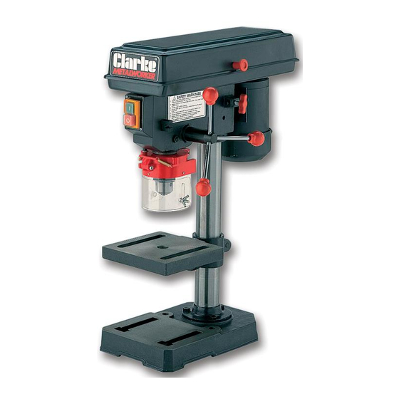
Clarke Metalworker CDP101B 운영 및 유지보수 매뉴얼 - 페이지 10
{카테고리_이름} Clarke Metalworker CDP101B에 대한 운영 및 유지보수 매뉴얼을 온라인으로 검색하거나 PDF를 다운로드하세요. Clarke Metalworker CDP101B 19 페이지. 13mm drill press

D. Chuck Guard Assembly
Slide the Chuck Guard over the Quill Shaft and nip up the pinch bolt, temporarily, with the
pinch bolt facing the front (see fig.4). Ensure the Quill Shaft/Spindle is at the top of its travel.
NOTE: This operation should be carried out before the chuck is installed.
E. Installing the Chuck.
1.
Slide the work table up the column to within 6" of the
spindle.
2.
Open the jaws of the chuck to their maximum, using
the chuck key supplied.
3.
Put a piece of scrap wood on to the table to protect
the chuck nose.
4.
Ensuring all parts are thoroughly clean, dry, and burr
free, place the chuck over the end of the spindle, and
pull the spindle down using the feed handles, pressing
the chuck hard against the piece of scrap wood
until the chuck is forced home.
5.
Slacken the chuck guard pinch bolt and turn the chuck guard so the the pinch bolt is
towards the rear and tighten the pinch bolt.
F. Belt Cover Knob.
Locate the knob, with pan head screw, and attach to the
cover, screwing on tightly.
G. Fitting the Drive Belt.
1.
Undo the Belt Tension Locking Screw (A, Fig.5), and,
referring to the chart inside the belt cover (which is
duplicated on page 12), fit the belt in the position
corresponding to the spindle speed required.
CHECKING THE OPERATION OF THE MICROSWITCH
When closing the cover, check the operation of the Microswitch. It is important that it
operates immediately the cover is pulled open, in order to prevent the machine from
operating........NOT when the cover is opened sufficiently for fingers to be inserted.
If necessary, bend the actuating tab, which is attached to the cover, to ensure this.
2.
Lever the motor, on its bracket, away from
the head, so that tension is applied to the
belt.Tension is correct, when the belt
deflects by approx. ½" at its centre, when
using reasonable thumb pressure. Lock the
motor in this position using the Locking
Screw.
NOTE: I f the belt should slip whilst drilling, adjust
the belt tension.
IMPORTANT:
Fig.6
10
Fig. 4
Fig. 5
