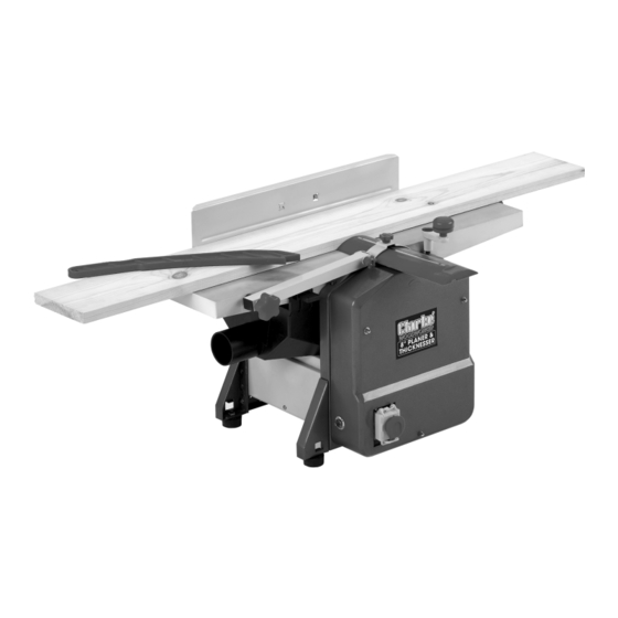
Clarke Woodworker CPT600 운영 및 유지 관리 지침 - 페이지 8
{카테고리_이름} Clarke Woodworker CPT600에 대한 운영 및 유지 관리 지침을 온라인으로 검색하거나 PDF를 다운로드하세요. Clarke Woodworker CPT600 18 페이지. Planer/thicknesser
Clarke Woodworker CPT600에 대해서도 마찬가지입니다: 운영 및 유지보수 매뉴얼 (18 페이지)

All manuals and user guides at all-guides.com
1. Attaching the Angle Fence
The peg - 'A' locates in the slotted
hole - 'B'. It may be necessary to screw
the peg down a little in order for the
peg to locate properly.
The Hex. socket head screw with
washers (in the bag of loose parts), is
used to secure the fence to the table,
through slot 'C', into threaded hole 'D'.
The fence may be set and locked at
any angle. Use a template or angle
gauge if accuracy is required.
2. Attach the Dust/Chip Extraction Chute
IMPORTANT: Please note that the Dust Chute MUST ALWAYS be in place, the machine
will not operate if is removed.
A. For Planing
A.1 Lower the Thicknesser Table as far as
possible by turning the Raise/Lower Knob
(see Fig.1) fully anticlockwise.
B. For Thicknessing
B.1 Remove the Angle Fence.
B.2 Push the Cutter Guard out of its
holder so that the Chute may be
attached to the table, as shown
in Fig.6.
Ensure both Locking keys are pushed
firmly into the slots in the table, shown
in Fig.5.
Fig. 5
A.2 Pull out the two Locking Keys (arrowed in
Fig.4) and manouvre the Chute into the
space beneath the table.
Ensure both Locking keys are pushed firmly
into the slots in the table, shown in Fig.5.
8
Fig. 3
Fig. 4
Fig. 6
