Clarke 7230650 운영 및 유지 관리 지침 - 페이지 7
{카테고리_이름} Clarke 7230650에 대한 운영 및 유지 관리 지침을 온라인으로 검색하거나 PDF를 다운로드하세요. Clarke 7230650 16 페이지.

A gate valve may be installed in-line on the delivery side of the pump which
can be set as required to regulate the flow of water. DO NOT place any such
restriction on the suction side of the pump unless it is an isolator valve in a
gravity fed system.
It is IMPORTANT to note also, that these pumps should not be operated with
the delivery valve completely closed.
To prevent unnecessary strain or possible distortion to the pump, ensure that
adequate support is provided to the hoses and/or pipes. Remember they will
be considerably heavier when filled with water.
Should sand, chemical or other contaminants come into contact with the
pump, flush through with cold clean water as soon as possible.
Protect the pump and pipework from freezing. The formation of ice may
cause serious damage.
Where the pump is to be a permanent fixture, the fittings to the pump MUST
be flexible, i.e. a short piece of hose should be inserted between rigid metal
pipework and the pump.
It is strongly recommended that in addition to the coarse foot filter, an inlet
filter should be fitted to prevent the possibility of foreign bodies entering the
pump.
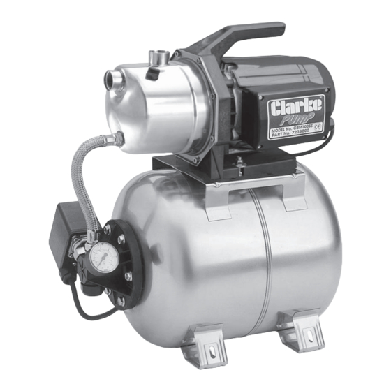
The CBM100SS units is set up as a BOOSTER pump by utilising an air chamber
with a pressure regulator to provide a constant pressure at the outlet. (for
optional accessories - see your Clarke dealer for details). If non-return valves
and filters are are used, they should be connected to the inlet port as follows:
1. Screw the non return valve into the inlet port, ensuring the arrow, stamped
on the valve, points towards the inlet port.
2. Tighten the valve, BUT DO NOT OVERTIGHTEN, then screw the filter on to
the valve - again DO NOT OVERTIGHTEN. The filter should hang vertically
when completed.
CBM100SS pump will automatically cut in when the water pressure reduces to
2.0 Bar, and cut out when the pressure reaches 3.5 Bar. These pressures are
factory set and must not be altered. The pump may continue to operate for
a short while after the tap is turned off, until the cut-out pressure is reached.
In order for the system to operate correctly, it is necessary to pressurise the air
chamber to 1.5 Bar (22psi), which is carried out as follows:
Unscrew the large protective cap on the end of the air chamber to reveal
the air valve, and use an air line or foot pump to charge the chamber to the
specified pressure, checking with a standard air pressure gauge until satisfied.
Remember to replace the protective cap when completed.
IMPORTANT: This procedure MUST be carried out BEFORE connecting to the
water supply.
7
