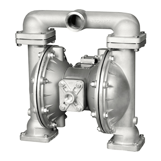
Alemite 8323-A 서비스 및 운영 매뉴얼 - 페이지 14
{카테고리_이름} Alemite 8323-A에 대한 서비스 및 운영 매뉴얼을 온라인으로 검색하거나 PDF를 다운로드하세요. Alemite 8323-A 19 페이지. Ball valve air-operated double diaphragm pump

DIAPHRAGM SERVICING
To service the diaphragms irst shut
off the suction, then shut off the
discharge lines to the pump. Shut off the
compressed air supply, bleed the
pressure from the pump and disconnect
the air supply line from the pump. Drain
any remaining liquid from the pump.
Step #1: See the pump assembly
drawing and the diaphragm servicing
illustration.
Using a 1/2" wrench or socket,
remove the 16 capscrews (item 9) that
fasten the manifolds (items 19 & 20) to
the outer chambers (item 13).
S t e p # 2 : R e m o v i n g o u t e r
chambers.
Using a 1/2" wrench or socket,
remove the 16 capscrews (item 10), that
fasten the outer chambers (item 13),
diaphragms (item 14) and intermediate
(item 5) together.
Step #3: Removing the dia-
phragms and diaphragm plates.
Use a 7/8" wrench or six point
socket to remove the outer diaphragm
plate assemblies (item 24), diaphragms
(item 14) and inner diaphragm plates
(item 23) from the diaphragm rod
(item 27) by turning counterclockwise.
Inspect the diaphragm for cuts, punctures,
abrasive wear or chemical attack.
Replace the diaphragms if necessary.
DO NOT USE A WRENCH ON THE
DIAPHRAGM ROD. FLAWS ON THE
SURFACE MAY DAMAGE BEARINGS
AND SEALS.
Alemite s1fmdl1sm-rev0211
S t e p # 4 : A s s e m b l i n g t h e
diaphragm and diaphragm plates to the
diaphragm rod.
Push the threaded stud of one outer
diaphragm plate assembly through the
center of one diaphragm and through
one inner diaphragm plate. Install the
diaphragm with the natural bulge facing
away from the diaphragm rod and make
sure the radius on the inner diaphragm
plate is towards the diaphragm, as
indicated on the diaphragm servicing
illustration. Thread the assembly onto
the diaphragm rod, leaving loose.
Step #5: Installing the diaphragm
and rod assembly to the pump.
Make sure the bumper (item 6) is
installed over the diaphragm rod. Insert
rod into pump.
On the opposite side of the pump,
pull the diaphragm rod out as far as
possible. Make sure the second bum-
per is installed over the diaphragm rod.
Push the threaded stud of the other
outer diaphragm plate assembly through
the center of the other diaphragm and
through the other inner diaphragm
plate. Make sure the radius on the inner
diaphragm plate is towards the
diaphragm. Thread the assembly onto
the diaphragm rod. Use a 7/8" wrench
or socket to hold one outer diaphragm
plate. Then, use a torque wrench to
tighten the other outer diaphragm plate
to the diaphragm rod to 500 in. lbs.
(56.5 Newton meters).
Align one diaphragm with the
intermediate and install the outer
chamber to the pump using the 8
capscrews. Tighten the opposite
diaphragm plate until the holes in the
diaphragm align with the holes in the
intermediate. Then, install the other
outer chamber using the 8 capscrews.
Step #6: Reinstall the manifolds to the
pump using the 16 capscrews.
The pump is now ready to be
reinstalled, connected and returned to
operation.
OVERLAY DIAPHRAGM SERVICING
The overlay diaphragm (item 15)
is designed to it over the exterior of the
standard diaphragm (item 14).
Follow the same procedures
described for the standard diaphragm
for removal and installation, except tight-
en the outer diaphragm plate assembly,
diaphragms and inner diaphragm plate
to the diaphragm rod to 500 in. lbs.
(56.5 Newton meters).
IMPORTANT
Read these instructions
c o m p l e t e l y, b e f o r e
installation and start-up.
It is the responsibility of
the purchaser to retain
this manual for reference. Failure to
comply with the recommendations stated
in this manual will damage the pump, and
void factory warranty.
Models 8323 & 8323-A Page 12
