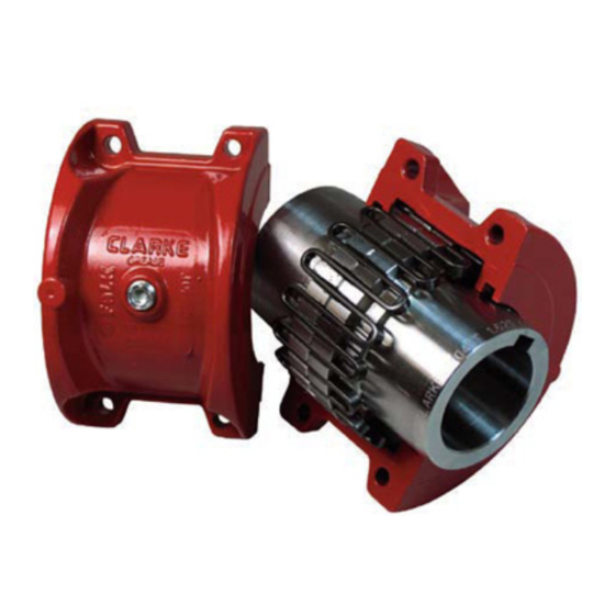
Clarke C10 제품 애플리케이션, 설치 및 서비스 매뉴얼 - 페이지 5
{카테고리_이름} Clarke C10에 대한 제품 애플리케이션, 설치 및 서비스 매뉴얼을 온라인으로 검색하거나 PDF를 다운로드하세요. Clarke C10 10 페이지. Electric motor driven fire pumps

ANNUAL MAINTENANCE
For extreme or unusual operating conditions, check
coupling more frequently.
1. Check alignment per steps on Page 3. If the maximum
operating misalignment limits are exceeded, realign the
coupling to the recommended installation limits.
Table 2 for installation and operating alignment limits.
2. Check tightening torques of all fasteners.
3. Inspect seal rings and gaskets to determine if
replacement is required. If leaking grease, replace.
4. When connected equipment is serviced, disassemble
the coupling and inspect for wear. Replace worn parts.
Clean grease from coupling and repack with new LTG
grease. Install coupling using new gaskets as instructed in
this manual.
Periodic Lubrication
Cover halves have 1/8" NPT lube holes.
Use a standard grease gun and lube fitting as instructed,
below.
The required frequency of lubrication is directly related to
the type of lubricant chosen, and the operating conditions.
Tapered grid couplings lubricated with common industrial
lubricants, such as those shown in Table 1, should be
relubed annually. The use of LTG Grease provided by
Clarke will allow relube intervals to be extended to
beyond five years. When relubing, remove both lube
plugs and insert a standard lube fitting in one of the 1/8"
NPT openings. Fill with recommended lubricant until an
excess appears at the opposite hole. CAUTION: Make
certain all plugs have been inserted after lubricating.
Coupling Disassembly and Grid Removal
Whenever it is necessary to disconnect the coupling,
remove the cover halves and grid.
screwdriver that will conveniently fit into the open loop
ends of the grid is required. Begin at the open end of the
grid section and insert the rod or screwdriver into the loop
ends. Use the teeth adjacent to each loop as a fulcrum
See
and pry the grid out radially in even, gradual stages,
proceeding alternately from side to side.
TYPE
C10,
INSTALLATION & ALIGNMENT DATA
Maximum life, reduced equipment vibration, and
minimum maintenance for the coupling and connected
machinery will result if couplings are accurately aligned.
Coupling life expectancy between initial alignment and
maximum operating limits is a function of load, speed and
lubrication. Maximum operating values listed in Table 2
are based on cataloged allowable rpm. Values listed are
based upon the use of the gaps listed, standard coupling
components, standard assemblies and cataloged allowable
speeds. Values may be combined for an installation or
operating condition.
operating misalignment is .016" parallel offset plus .018"
angular.
Angular misalignment is dimension x minus y as
illustrated below.
between the hub center lines as illustrated below. End
float (with zero angular and parallel misalignment) is the
axial movement of the hub(s) within the cover(s)
measured from "0" gap.
Page 5 of 10
A round rod or
C31
and
C35
COUPLING
Example:
C1060T maximum
Parallel misalignment is distance P
