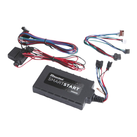
Directed Electronics SMARTSTART DSM200 빠른 참조 설치 매뉴얼
{카테고리_이름} Directed Electronics SMARTSTART DSM200에 대한 빠른 참조 설치 매뉴얼을 온라인으로 검색하거나 PDF를 다운로드하세요. Directed Electronics SMARTSTART DSM200 2 페이지.

Installation Procedure
This product is compatible with all Directed Electron-
ics Security, Remote Start and hybrid systems that are
Bitwriter™ (3 or 4 pin) compatible:
CAUTIONS: Cable connectors and their
associated ports are the same color. Con-
necting to the wrong port can damage
the unit.
DO NOT connect the white 4-pin D2D
connector to brown ESP port on Directed
systems.
DO NOT connect the black 3-pin ESP con-
nector to white Door Lock port on Direct-
ed systems.
The white connector cannot be connected
to Xpresskit module except in standalone
Datastart applications as shown below.
For all ESP systems, connect Xpresskit
module to the Directed system, not to the
SmartStart Y-adapter.
Please read the following before proceeding
1. Customer Information required:
•
Record the customer information requested
ESP (4 pin, brn)
4 pin
ESP (3 pin, blk)
SmartStart Module
D2D (4 pin, wht)
(Top view)
Fuse
2 pin
+12V
GND
NOTE: The appearance and connector/port arrangement on the
Directed/Avital/Xpresskit system may di er to the examples shown .
SmartStart Module to Xpresskit
¢
cut loop (see table)
4 pin
Directed System
(Top view)
LED
D2D
(4 pin, white)
2 pin
+12V
GND
in step 5a of this procedure. The module ID
# is provided on a sticker which can be af-
fixed to the space provided in step 5a.
•
Is this a new account or one being added to
an existing account? Check box(es) in 5a.
This information is required for final verification/
activation of the VSM200/DSM200.
2. Installation Points:
•
Install and test the security/remote start sys-
tem first using the associated guides and
wiring diagram. If using an existing system,
verify it is fully functional before installing the
Directed SmartStart module.
•
For 3000-series Remote Start systems with
no supplied remote control, test the installed
system using the functional commands in the
SmartStart activation portal.
•
Mount the SmartStart module as high as pos-
sible in the vehicle (side with color label up).
Mount with minimal obstructions that can
affect communications and within reach of
the main Directed system using the provided
cables (do not extend).
•
DO NOT connect the SmartStart module un-
til the final programming of the Remote Start
main unit and verification of security/remote
start system operations are completed.
3. Install the VSM200/DSM200 using the informa-
ESP (4 pin, brn)
4 pin
ESP (3 pin, blk)
D2D (4 pin, wht)
Fuse
2 pin
+12V
GND
White
Brown*
Closed
Closed
SmartStart Module to Xpresskit
Closed
Open **
* This wire color may be blue on some units.
¢
cut loop (see table)
**If a loop is cut, the module must be powered off
4 pin
and then on again to initiate this state change.
Quick Reference
Install Guide
VSM200/DSM200
Directed System
(Top view)
Communication Type
2-way ESP
2-way D2D
D2D
(4 pin, white)
QRNDSM200 2010-08
2 pin
+12V
GND
