Clarke CONTRACTOR CHJ110 운영 및 유지보수 지침 매뉴얼 - 페이지 5
{카테고리_이름} Clarke CONTRACTOR CHJ110에 대한 운영 및 유지보수 지침 매뉴얼을 온라인으로 검색하거나 PDF를 다운로드하세요. Clarke CONTRACTOR CHJ110 10 페이지. Hinge jig

Operation
Before commencing:
ALWAYS ensure the work area is safe and secure.
ALWAYS ensure the door is supported properly, ideally using a folding workbench or similar.
ALWAYS ensure the router path is clear of any obstacles etc.
ALWAYS ensure the router power cable is clear of the jig and is of sufficient length.
ALWAYS read and understand the router instruction manual to ensure safe operation.
Jig Assembly
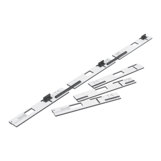
Select the plates required either 3" or 4".
Attach the aligning/clamping sets using nuts and screws
supplied (Fig. 1), ensure the square nut sits in the recess,
DO NOT fully tighten screws, leave loose enough to allow
the clamping sets to slide backwards and forwards for
adjustment later.
Join plates using the adjustable connecting bars.
Attach both bars to the middle plate first and firmly secure
with wing screws (Fig. 2).
Attach top and bottom plates leaving wing screws loose
to enable adjustment
Wing Screw
Connecting Bar
Top/Bottom Plate
Fig. 4
Wing Screw
Middle Plate
Fig. 2
Setting Width Of Hinge Recess
1. Slide the alignment/clamping block to the back
of the plate.
2. Position the knuckle of the hinge in the slot
opposite the alignment/clamping block as in
Fig. 4.
3. Push the alignment/clamping block against the
edge of the hinge as in Fig. 4.
4. Tighten the alignment/clamping block securing
screw.
5. Repeat steps, 1,2,3 &4 for the remaining
alignment/clamping sets.
Fig. 1
NOTE: ONLY the Top and Bottom
plates are adjustable, and can be
easily removed from assembly by
simply loosening the wing screw
and sliding the plate in direction
of arrow (Fig. 3) this allows the wing
screw to pass through keyhole.
Fig. 3
-4-
