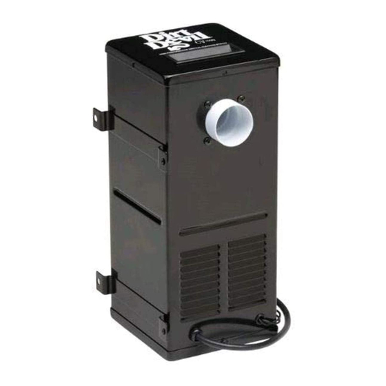
Dirt Devil CV1500 소유자 매뉴얼 - 페이지 6
{카테고리_이름} Dirt Devil CV1500에 대한 소유자 매뉴얼을 온라인으로 검색하거나 PDF를 다운로드하세요. Dirt Devil CV1500 13 페이지. Central vacuum systems
Dirt Devil CV1500에 대해서도 마찬가지입니다: 빠른 설치 매뉴얼 (2 페이지)

INSTALLATION INSTRUCTIONS
3. Determine valve location and cut 2 1 /4"
(58mm) wide x 3 3 /4" (95mm) high
opening, 9 7 /8" (251mm) above the floor
(Fig C) for upright canister position or
1 3 /4" (45mm) above floor for horizontal
canister position (see fig D).
4. Do not vent into a wall, ceiling or con-
cealed space of a building or structure.
Unit must be vented with interior vent
or equivalent (see fig D).
5. Place the CV1500 canister in its approxi-
mate location before installing inlet valve
(4940), mounting plate (4865), and
inlet reducer (5531) (see fig. E).
6. Inlet valve switch should be wired at this
point for convenience (See Figure E). In-
sert pre-stripped ends of 18-2 (1.00 mm-
2) low voltage wire into holes on back
of inlet valve (4940), press in firmly and
wires will lock automatically. Pull lightly
to test for locking. Connect other ends
of wire from inlet valve to wire leads
from relay (7090) with wire nuts provided.
7. Install inlet reducer (5531) to inlet con-
nector (7464), glue if needed. Assemble
inlet valve to wall with mounting plate
(4865) using the four screws provided
(see Figure E). Also, tabs on mount-
ing plate should face away from inlet valve.
8. Secure unit to floor and or wall with
mounting screws provided.
9. Plug in power cord from
motor unit to nearby elec-
trical receptacle. Route
power supply cord so that
it doesn't rest against
sharp edges or pinch
points. The CV1500
unit operates when the
inlet valve lid is lifted.
Wire
4940, 4935, 4941
Inlet Valve
4865 Mounting Plate
5
continued...
6452-05
5531 Inlet Reducer
1¹⁄₄" Hose Cut to Length
Wire
Figure: C
Figure: D
Figure: E
7477-G
Flex Connector Kit
(3 Fittings)
CV1500
