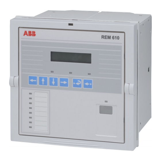
ABB REM 610 설치 매뉴얼 - 페이지 15
{카테고리_이름} ABB REM 610에 대한 설치 매뉴얼을 온라인으로 검색하거나 PDF를 다운로드하세요. ABB REM 610 20 페이지. Motor protection relay
ABB REM 610에 대해서도 마찬가지입니다: 제품 설명서 (16 페이지), 제품 설명서 (17 페이지)

1MRS 752265-MUM
0RWRU 3URWHFWLRQ 5HOD\
Installation Manual
&RQQHFWLRQV
Connection terminals are described in the Technical Reference Manual. Each
contact has its own identification number, X2.1, for instance. The numbering of the
contacts runs from top to bottom, except the connectors X2.1 and X5.5 which are
numbered from bottom to top; see
Terminal blocks of screw-compression and ring-lug type are used for electrical
connections while transceivers of snap-in type are used for plastic fibre-optic
connections. If terminals of screw-compression type are used:
1. Open the screw terminal before inserting a wire into it for the first time. To open
the screw terminal, turn the fixing screw anticlockwise until the terminal hole is
wide open (the inside of the terminal hole is surrounded by metal).
2. Insert the wire and turn the fixing screw clockwise until the wire is firmly fixed.
Only use screwdriver and insert bits for Phillips (PH 1) cross-recessed head screws
(M3.5) when handling CT terminals (X2.1) of screw-compression type.
A)
5.5 mm
MAX
)LJ 6FUHZGULYHU DQG LQVHUW ELWV IRU &7 WHUPLQDOV RI VFUHZFRPSUHVVLRQ W\SH
It is also possible to use terminals of ring-lug type for the CTs. If using terminals of
ring-lug type:
1. Open the lid that covers the ring-lug fixing screw (every fixing screw has its
own lid) with the tip of a screwdriver.
2. Screw off the screw, slide it through the terminal lug and screw it back on.
3. Close the lid.
When the wires for the CTs have been connected, install the snap ferrite ring,
provided with the relay, around the wires as close to the relay terminals as possible.
(OHFWULFDO FRQQHFWLRQV
All connections are made on the rear of the case. No soldering is needed.
Each signal connector (X3.1 and X4.1) terminal is dimensioned for one 0.2...2.5
2
mm
wire or two 0.2...1.0 mm
Connect the wires from the CTs to the right device according to the phase order and
the coupling scheme. Each terminal for CTs is dimensioned for one 0.5...6.0 mm
wire or for two maximum 2.5 mm
A separate earth lead of at least 2.5 mm
earth screw between connectors X4.1 and X3.1 (upper screw; see
earth bar.
.
Fig. 5.1.-1
B)
C)
2
wires.
2
wires.
2
has to be connected from the protective
5(0
D)
2
) to the
Fig. 5.1.-1
15
