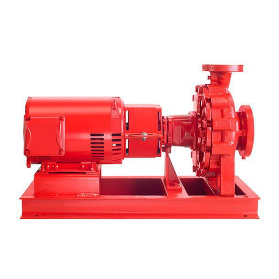
Armstrong 4030 설치 및 운영 지침 매뉴얼 - 페이지 6
{카테고리_이름} Armstrong 4030에 대한 설치 및 운영 지침 매뉴얼을 온라인으로 검색하거나 PDF를 다운로드하세요. Armstrong 4030 12 페이지. Base mounted pump
Armstrong 4030에 대해서도 마찬가지입니다: 설치 및 운영 지침 매뉴얼 (12 페이지)

i nstal l a ti o n &
o p er ati ng i nstru ct ion s
6
2 . 4 grouting
After levelling the unit and checking the alignment. Fill the
baseplate completely with grout, allowing it to flow around
the wedges under the baseplate. Allow 48 hours for the
grout to harden before final tightening of the foundation
bolts.
2 .5 piping
Both the suction and discharge pipes should be indepen-
dently supported near the pump so that no strain is imposed
on the pump when the pipes are connected. All connecting
pipework should be accurately located – do not attempt to
force the suction and discharge pipes into position.
Suction Piping
Use short direct suction piping one or two times larger than
the pump suction nozzle. Arrange piping to eliminate poten-
tial air pockets and use an eccentric reducer to connect to the
suction nozzle. A strainer three or four times the area of the
suction pipe will prevent foreign materials entering the pump.
Discharge Piping
A check valve and gate valve should be installed in the
discharge line. If an increaser is used on the discharge side
to increase the size of the discharge pipe it should be placed
between the check valve and the pump.
2 .6 final alignment
When the piping has been connected, check the alignment
and make corrections if necessary. Energise the motor (with
coupling halves disconnected) and check that the rotation
corresponds with the direction arrow on the pump to reverse
the rotation on a three-phase motor, interchange two leads.
When rotation and alignment are correct, re-connect the
coupling with both halves butting against the rubber insert.
Tighten the coupling set screws.
3 .
pump piping - gener al
• Never connect a pump to piping, unless extra care is
taken to measure and align the piping flanges well.
Always start piping from pump. Use as few bends as
possible and preferably long radius elbows.
• Ensure the piping exerts no strain on the pump as this
could distort the casing causing breakage or early failure
due to pump misalignment.
• All connecting pipe flanges must be square to the
pipework and parallel to the pump flanges.
Series 4030
Base mounted pump
• Suction and discharge pipes may be increased or
decreased at the pump nozzle to suit pump capacity
and particular conditions of installation. Use eccentric
reducers on suction connection with flat side uppermost.
• Layout the suction line with a continual rise towards the
pump without high points, thus eliminating possibility of
air pockets that may prevent the pump from operating
effectively.
• A strainer of three or four times the area of the suction
pipe, installed in the suction line, will prevent the entrance
of foreign materials into the pump. 5mm diameter
perforations in the strainer is typical.
• In open systems, test suction line for air leaks before
starting; this becomes essential with long suction line or
static lift.
• Install, at the pump suction, a straight pipe of a length
equivalent to 4 or 6 times its diameter; this becomes
essential when handling liquids above 49°c ( 120°f ).
Armstrong suction guides may be used in place of the
straight pipe run and in-line strainer.
• Install an isolation valve in both suction and discharge
lines on flooded suction application; these valves are used
primarily to isolate the pump for inspection or repair
• Install a non-slam non-return check valve in discharge line
between pump and isolation valve to protect pump from
excessive back pressure and to prevent water running
back through the pump in case of driver failure on open
systems. An Armstrong Flo-Trex valve may be used in
place of non-return check valve and isolation valve on
pump discharge.
caution:
The discharge valve only is to be used to throttle
pump flow, not the suction valve. Care must be
taken in the suction line layout and installation, as it
is usually the major source of concern in centrifugal
pump applications.
oper ation
4 .
starting pump
• Ensure that the pump turns freely by hand, or with some
mechanical help such as a strap and lever on larger
pumps. Ensure that all protective guarding is securely
fixed in position.
• The pump must be fully primed on start up. Fill the pump
casing with liquid and rotate the shaft by hand to remove
any air trapped in the impeller.
• Bump or energize the motor momentarily and check that
the rotation corresponds with the directional arrow on the
pump casing.
