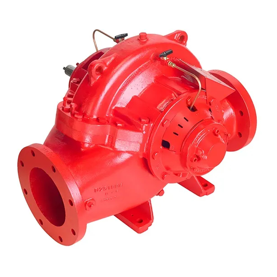
Armstrong 4600 HSC series 설치 및 운영 지침 매뉴얼 - 페이지 11
{카테고리_이름} Armstrong 4600 HSC series에 대한 설치 및 운영 지침 매뉴얼을 온라인으로 검색하거나 PDF를 다운로드하세요. Armstrong 4600 HSC series 16 페이지. Horizontal split case fire pumps. 12x8x18f

4.3 removal of impeller ring
It is not necessary to remove impeller from shaft to replace
impeller rings
1. Remove rotating element
2. Remove locking set screws from rings
3. Rings may now be pulled from impeller, cut off with a chisel,
or turned off if a suitable lathe is available using original shaft
centers - do not cut into body of impeller
4. When new rings are installed, drill and tap new holes for locking
set screws - do not attempt to use old half holes in impeller hub
4.4 inspection
1. Visually inspect parts for damage affecting serviceability
2. Check o-rings and gaskets for cracks, nicks or tears
3. Check packing rings for excessive compression, fraying or
shredding and embedded particles
4. Replace if defective in any way
5. Mount shaft between the lathe centers to check eccentricity
throughout the entire length, runoff should not exceed 0.002".
6. Bearing surface should be smooth and shoulders square and
free of nicks
7. Measure od of impeller hub or impeller wear rings and id of
casing wear ring
8. Compute diametrical clearance (id minus od) and compare
with original (0.0075" to 0.0085") radial clearance
9. Surfaces must be smooth and concentric
10. Examine impeller passages for cracks, dents or embedded
material
11. Examine shaft sleeves for wear
4.5 assembly is the reverse of the
disassembly procedure
1. All parts, inside and out, should be clean since dirt and grit will
cause excessive wear, plus needless shutdown
2. Reinstall sleeve in correct position - 12½" from bearing face to
sleeve face (see drawing pump assembly)
3. Reinstall impeller with vanes in right direction - impeller vanes
slope must be opposite to pump rotation
Horizontal split case
fire pumps
Pump rotation is defined viewed from the driver's end
1. Do not lock sleeve shaft with impeller key until impeller has
been positioned in center of volute; this may be accom-
plished by moving sleeve. Thread of both sleeves as well as
locking setscrews to be applied with Loctite 242. Once locked
sleeve is in position, torque the other sleeve with 100 ft.lb.
Then tighten (4) setscrews in both sleeves with 11 ft.lb torque.
2. Make certain that casing rings are in proper position; the
half raised ring should be on the outside and completely in
the lower half casing and ensure ring is fully seated
3. Install casing gasket and do not cut overlap before casing
cover is in place and bolted
4. Install upper half, cut gasket on each side of the stuffing box
and bore after all cap screws are tightened
5. Install stuffing box bracket and packing afterwards. Insure
that packing does not block seal water inlet
6. Install packing flush line
7. Reinstall bearings and bearing covers
12½
3050pk1.prt
sleeve locking setscrews
i n s ta l l at i o n &
o p e r at i n g i n s t r u c t i o n s
bearing removal nut
grease cavity
bearing cover
bearing
bearing removal nut
11
