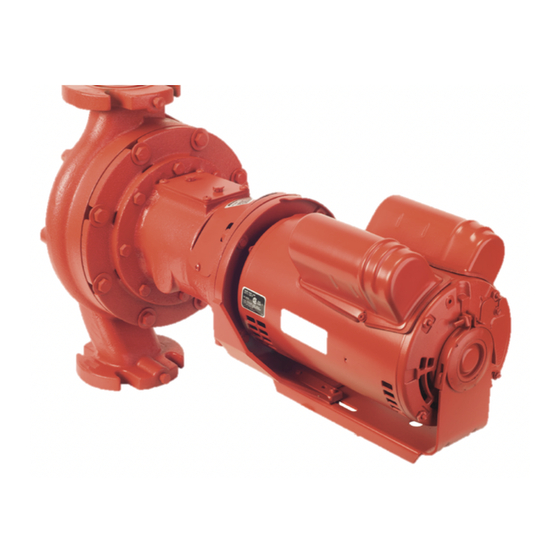
Armstrong H63 설치 및 작동 지침 - 페이지 6
{카테고리_이름} Armstrong H63에 대한 설치 및 작동 지침을 온라인으로 검색하거나 PDF를 다운로드하세요. Armstrong H63 10 페이지. In-line ecm circul ating pumps

i n stal l a t io n &
o p era t ing i nstruct ion s
6
Using 0 V to 10V DC signal
Vdc Connector
0 -10
part #
D50 040 0 -3 01
2 troubleshooting
This section provides field technicians with a step-by-step
process for accurately diagnosing and troubleshooting difficul-
ties that may be experienced by nmc PerfectSpeed® motors
and the PerfectSpeed User Interface box. It does not override
or replace instructions suggested by the manufacturer of the
fluid circulating system.
To prevent misdiagnosis and unneeded repairs of the motor,
operators should try the steps listed in the Basic Troubleshoot-
ing of the Motor section first. If a problem still exists or there is
an ongoing issue after following the outline in that section, then
proceed to the Motor and Control Unit Diagnostics section for
additional testing instructions.
Basic troubleshooting of the motor
notice
• Always begin your inspection of the motor by stepping
through this section.
Motor is not spinning or runs abnormally
• Check the circuit breaker for trips or accidental shutoff.
• Verify that the cables and power cord are securely con-
nected to the control unit connectors.
• Inspect for shorts, detached wiring, or loose connections.
• Inspect the control unit for broken or loose connectors,
moisture, excessive dirt, or other damage.
Motor rattles or makes excessive noise
• Inspect the motor and pump for accumulated dirt, internal
debris, or other signs of damage.
• Inspect the shaft and verify that the motor shaft spins freely
by hand in both directions without effort.
In-line circulating
pumps
PerfectSpeed® motor and user interface
Motor is not running
If the PerfectSpeed® motor with User Interface isn't running,
perform the following checks:
1 Ensure that both the PerfectSpeed® motor and User Inter-
face have proper line voltage for intended application.
2 Turn the User Interface on-board potentiometer fully clock
wise (100% demand) and check to see if the motor runs.
3 If 0V to 10V DC input is in use, disconnect the external input
from the User Interface and perform Check 2.
4 Check the digital read- out of User Interface for an error code:
Table 5 – User interface error codes
error
reason
action
code
e1
No
Remove power from both the PerfectSpeed®
Communication
motor and user interface for four (4) min-
utes, then reconnect power and test again.
Check the communication cable
con nection between the PerfectSpeed® mo-
tor and user interface.
Check the continuity of the communication
cable (pin 1-1, pin 2-2 pin 3-4, and pin 4-3).
e2
Low Voltage
This is a reading from the PerfectSpeed®
motor itself. Ensure that there is at least 71V
AC (for 115V AC applications) or 142V AC
(for 208-230V AC applications).
e4
Not a nmc
Connect to a nmc motor.
Motor
Motor and control unit diagnostics
Check 2: Electrical troubleshooting
1 Disconnect or remove power to the equipment being
serviced and allow four (4) minutes for the capacitors to
discharge any residual voltage.
2 Check the rotation and speed of the motor. Determine
if the motor can spin freely by hand without effort or as-
sisted means. If any binding occurs, replace the motor and
control unit.
3 Determine whether the system is wired for 120V AC power
or 240V AC power.
4 Disconnect the power cord from the connector on the
control unit. Inspect the power cord for bent, damaged, or
recessed wired and terminals [fig 1].
