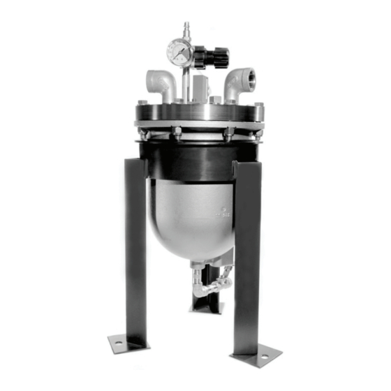
Blacoh SPILLSTOP 설치 및 운영 매뉴얼 - 페이지 4
{카테고리_이름} Blacoh SPILLSTOP에 대한 설치 및 운영 매뉴얼을 온라인으로 검색하거나 PDF를 다운로드하세요. Blacoh SPILLSTOP 8 페이지. Leak containment system
Blacoh SPILLSTOP에 대해서도 마찬가지입니다: 설치 및 운영 매뉴얼 (12 페이지)

Service
The SPILLSTOP must be serviced after every shutdown before being put back into operation. To service the SPILLSTOP:
1. Disconnect all air supply to the pump and SPILLSTOP.
2. Remove the SPILLSTOP lid and flush internal areas with water or cleaner appropriate for the process fluid being
pumped.
3. Test the SPILLSTOP shutoff valve ② before reassembly:
a. Connect an air line to the SPILLSTOP regulator ① .
b. Disconnect the plastic tube at the pump shutoff valve ② .
c. Adjust the SPILLSTOP regulator ① to a minimum of 40 psi (2.7 bar). Air should now be flowing through the tube.
d. Push the float ⑤ up to activate the SPILLSTOP. Air should stop flowing through the tube. If air does not stop flowing,
the SPILLSTOP shutoff valve ② has been damaged and should be replaced.
4. Reassemble the SPILLSTOP and adjust the regulator ① to a minimum of 40 psi (2.7 bar) to restart the pump. If the
SPILLSTOP is installed with optional whistle, switch and/or a second pump shutoff valve for a backup pump, increase
pressure to a minimum of 60 psi (4.1 bar).
Maintenance
The SPILLSTOP is normally maintenance free; however, a function test should be performed at least every 90 days to
ensure proper operation. To perform a function test:
1. Turn off all air supply to the pump and SPILLSTOP.
2. Open the test port plug ⑪ on the SPILLSTOP lid and fill the SPILLSTOP with approximately 2 cups (.47L) of water.
3. Turn on the air supply to the pump and SPILLSTOP and adjust the SPILLSTOP regulator ① to a minimum of 40 psi (2.7
bar). The pump should not operate.
4. Turn off all air supply to the pump, drain the SPILLSTOP and replace the test port plug ⑪ .
5. Turn on the air supply to the pump and SPILLSTOP. The pump should now operate normally.
Optional Whistle Kit Instructions
Installed on port 4 of the SPILLSTOP's 3-way pneumatic actuator valve ⑥ , the optional whistle will sound an auditory alarm
alerting personnel that the primary pump has failed and SPILLSTOP has shutdown the pump (Figure 1). When SPILLSTOP
triggers a pump shutdown, air pressure is shifted from port 2 to port 4 of the 3-way pneumatic actuator valve to pneumatically
power the whistle. The Whistle Kit ⑩ (P/N 50-98K) includes a whistle, a tube tee and 15 feet of 1/4" tubing.
1. The whistle comes pre-installed from the factory if purchased with the SPILLSTOP. If purchased separately, install by
attaching the whistle to the tubing and connect to port 4 of the 3-way pneumatic actuator valve ⑥ . If there is a second
shutoff valve for a backup pump installed, the whistle must be installed using the tube tee including with the kit. Insert
the tube at any point in the tubing connecting port 4 to the shutoff valve on the backup pump and install the whistle on a
branch of the tube tee.
IMPORTANT! The length of tube from the tee to the whistle must be the same length as the length of tube
from the tee to the switch and/or backup pump. The whistle consumes a high volume of compressed air and
if not installed properly can prevent the switch and/or backup pump from activating.
2. Test the whistle before putting the SPILLSTOP into operation:
a. Connect an air line to the SPILLSTOP regulator ① .
b. Adjust the SPILLSTOP regulator ① to a minimum of 40 psi (2.7 bar).
c. Push the float ⑤ up to activate the SPILLSTOP. Air should start flowing through the tube connected to port 4 of the
3-way pneumatic actuator valve ⑥ and the whistle should sound.
3
TM
BLACOH Fluid Control
