Abbey swampfox SF1 설치 매뉴얼 - 페이지 6
{카테고리_이름} Abbey swampfox SF1에 대한 설치 매뉴얼을 온라인으로 검색하거나 PDF를 다운로드하세요. Abbey swampfox SF1 8 페이지. Pump station controller

Speaker / Microphone Connections
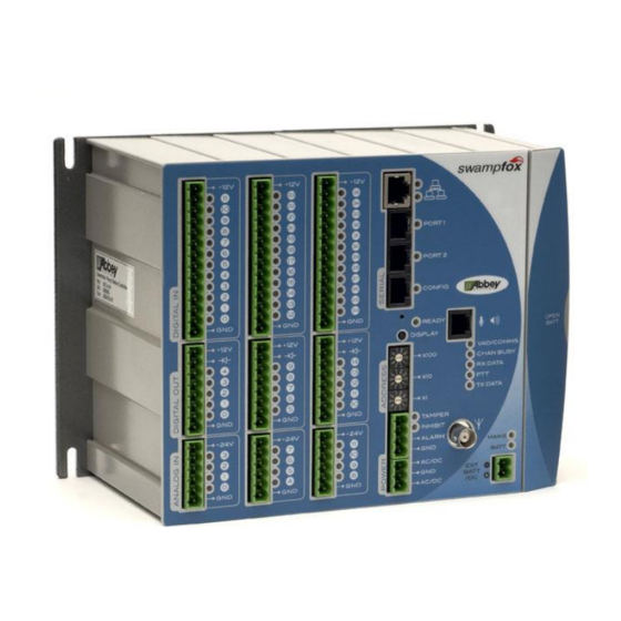
A suitable Speaker / Microphone connection is provided on units with an internal
radio for monitoring and testing the radio channel.
Communication Indicators
The
indicators show communication between
COMMS
Master.
Indicator
Indication
VAD/COMMS
Green short blink
Green long blink
Red
CHAN BUSY
Yellow
RX DATA
Yellow
PTT
Yellow
TX DATA
Yellow
A short blink is about 0.1 seconds. A long blink is about 0.5 seconds.
Ready LED and Reset
Ready LED indication
Green
Red
The COMMS LED (if present) above the Ready LED lights red when f is in comms
fail to a master.
The
button is behind a small unmarked hole in the front panel near the
RESET
button. To reset and restart
DISPLAY
Installation Guide
Pin Name
1
N/C
2
Speaker
3
PTT
4
Microphone
5
GND
6
GND
Meaning
A valid message for a different RTU was received
A valid message for this RTU was received
Comms fail (no comms with the Master)
The radio transceiver is receiving RF on it's channel
Shows the data being received by swampfox
swampfox is transmitting on the radio channel
Shows the data being transmitted by swampfox
swampfox operating state
Normal swampfox is operating normally
Defect
Hardware or firmware fault
swampfox
6
1
RJ12 Speaker Mic Pins
swampfox
, press
RESET
5
and the Telemetry
briefly.
IG-619-2.2-2015-Mar
